How to Measure Electrical Power
If a product uses power, then power consumption and power quality measurements must be a part of product design and test. These measurements are essential to optimize product design, comply with standards, and provide nameplate information to customers. But how do you measure electricity?
This article will discuss best practices to measure electrical power, starting with power measurement basics and proceeding to the types of instruments and associated components typically used to make measurements. The article will conclude with real-world examples, which apply the information imparted earlier in the article to solve practical measurement problems.
Although most of us have been exposed to basic power measurement equations, a primer is helpful to summarize this information and to show how it applies to product design and test.
Power Measurement Basics
How is electrical current measured?
DC power measurement is relatively simple as the equation is simply watts = volts x amps. For AC electrical power measurement, the power factor (PF) introduces complexity as watts = volts x amps x PF. This measurement of AC power is referred to as active power, true power, or real power. In AC systems, multiplying volts x amps = volt-amps, also called apparent power.
Power consumption is measured by calculating it over time, using at least one complete cycle. Using digitizing techniques, the instantaneous voltage is multiplied by the instantaneous current then accumulated and integrated over a specific time period to provide a measurement of electrical current. This method provides a true power measurement and true RMS measurements for any waveform, sine or distorted, including harmonic content up to the bandwidth of the instrument.

Single-phase and Three-phase Power Measurement of Electrical Power
The Blondel Transformation states that total power is measured with one less wattmeter than the number of wires in the system. Therefore, a single-phase, two-wire system will require one wattmeter, a single-phase, three-wire system will require two wattmeters (Figure 1), a three-phase, three-wire system will require two wattmeters, and a three-phase, four-wire system will require three watt meters.
What Device Measures Current?
 |
 |
Figure 1. The two-wattmeter method can measure power through direct connections to a 3P3W system. Pt = P1 + P2
In this context, a wattmeter is a device used to measure current via one current and one voltage input. Many Power Analyzers and DSOs have multiple current/voltage input pairs capable of measuring watts, in effect acting as multiple wattmeters within a single instrument. Thus, it’s possible to measure three-phase 4-wire power with one correctly specified Power Analyzer.
With a single-phase, two-wire system (Figure 2), the voltage and current detected by the wattmeter are equal to the total power dissipated by the load. The voltage is measured between the two wires, and the current is measured in the wire supplying power to the load, often called the hot wire. Voltage can typically be measured directly by a Power Analyzer up to 1000 V RMS. Higher voltages will require the use of a VT (Voltage Transformer) on an AC system to step down the voltage to a level that can be measured by the instrument. Currents can typically be measured directly by a Power Analyzer up to 50 A, depending on the instrument. Higher currents will require the use of a CT (Current Transformer) on an AC system. There are different types of CTs. Some are placed directly in-line. Others have a window which the current-carrying cable passes through. The third kind is a clamp-on type. For DC currents, a shunt is typically used. The shunt is placed in line and a low level millivolt signal is measured by the instrument.
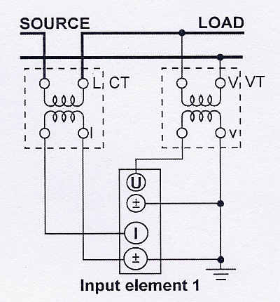
Figure 2. A single-phase, two-wire system uses a current transformer and voltage transformer.
With a single-phase, three-wire system (Figure 3), the total power is the algebraic sum of the two wattmeter readings. Each wattmeter is connected from one of the hot wires to the neutral, and current is measured in each hot wire. Total Power is calculated as Pt = P1 + P2.

Figure 3. Two wattmeters connect to a single-phase, three-wire system (1P3W).
With a three-phase, four-wire system (Figure 4), the three wattmeters each measure voltage from a hot wire to the neutral, and each wattmeter measures current in one of three hot wires. The total power for the three phases is the algebraic sum of the three wattmeter measurements, as each meter is in essence measuring a single phase of the three-phase system. Pt = P1 + P2 + P3
 |
 |
Figure 4. This three-phase, four-wires system uses three wattmeters.
With a three-phase, three-wires system (Figure 5), the two wattmeters measure phase current in any two of three wires. Each wattmeter measures a line-to-line voltage between two of the three power supply lines. In this configuration, the total power, watts is accurately measured by the algebraic sum of the two wattmeter values. Pt = P1 + P2. This holds true if the system is balanced or unbalanced.
If the load is unbalanced, meaning that the phase currents are different, total power will be correct, but the total VA and power factor could be in error. Power analyzers, though, may have a special 3V3A wiring configuration to ensure accurate measurements on three-phase, three-wire systems with a balanced or unbalanced load. This method uses three watt meters to monitor all three phases. One wattmeter measures voltage between the R and T phases, a second wattmeter measures voltage between the S and T phases and a third wattmeter measures voltage between the R and S phases. The phase currents are measured by each wattmeter. The two-wattmeter method is still used to calculate total power. Pt = P1 + P2. The total VA, however, is calculated as (√3/3)(VA1 + VA2 + VA3). All three voltages and currents are used to make accurate measurement and calculations on the unbalanced load.
 |
 |
Figure 5. A three-phase, three-wire system uses the three-wattmeter method to achieve accurate measurements on an unbalanced load.
Power Factor Measurement
Power factor must often be measured, and this value should be kept as close as possible to unity (1.0).
In an electric power system, a load with a low power factor draws more current than a load with a high power factor for the same amount of useful power transferred. The higher currents increase the energy lost in the distribution system and require larger wires and other equipment. Because of the costs of larger equipment and wasted energy, electrical utilities will usually charge a higher cost to industrial or commercial customers exhibiting a low power factor.
Figure 6 shows current lagging voltage by 44.77°, which gave a power factor of 0.70995. The apparent power, S1, was 120.223 VA. The true power, or real power, P1, however, was only 85.352 W.

Figure 6. A power analyzer screen shows a phase difference between voltage and current.
If power-consuming devices have good power factors, then the entire power system will as well, and vice versa. When power factors drop, power-factor-correction devices must often be used, at considerable expense. These devices are typically capacitors because the bulk of most power-consumption loads are inductive.
The current lags the voltage in an inductor; this is known as a lagging power factor. The current leads the voltage in a capacitor; this is known as a leading power factor. An AC motor is an example of an inductive load, and a compact fluorescent lamp is an example of a capacitive load.
To determine total power factor on a three-phase 4-wire system, three wattmeters are required. Each meter measures watts, and measurements are also made of the volts and amps. The power factor is then calculated by dividing the total watts from each meter by the total volt-amps.
With a three-phase, three-wire system, power factor should be measured using the three wattmeter method instead of the two wattmeter method if the load is unbalanced, that is, if the phase currents are different. Because the two wattmeter method only makes two amp measurements, any differences in the amp reading on the third phase will cause inaccuracies.
Household Appliance Power Measurement
A typical application for power measurement is standby power for household appliances that are based on Energy Star or IEC62301 standards. Both standards define the required power accuracy, resolution and other power measurement parameters, such as harmonics. Within the IEC62301 standard, there are an additional 25 standards that define the specific test parameters for various appliances. For example, IEC60436 defines the methods for measuring the performance of electric dishwashers.
Standby mode is defined as the lowest power consumption mode that cannot be turned off by the user and that may persist for an indefinite time when an application is connected to the main electricity supply and used in accordance with the manufacturer’s instructions. Standby power is the average power in standby mode when measured in accordance with the standard.
There are three main methods to measure power consumption for standby power or other similar applications. If the power value is stable, then the instantaneous instrument reading at any point in time can be used. If the power value isn’t stable, then take either an average of the instrument readings over time or measure total energy consumption. Watt-hours can be measured over a specified period of time and then divided by that time.
Measuring total-energy consumption and dividing by time yields the most accurate values with both steady and fluctuating power and is the method commonly employed when using our Power Analyzers. But measuring total energy consumption requires a more sophisticated instrument because power must be continuously measured and totalized.
Tools for Power Measurement
Power is typically measured with a digital power analyzer or a DSO (digital storage oscilloscope) with power-analysis firmware. Most modern power analyzers are entirely electronic and use digitizers to convert analog signals to digital forms. Higher end analyzers use digital signal processing techniques to make the calculations required to determine values.
Power-analysis DSOs use special firmware to make true power measurements. They are, however, somewhat limited because they rely on sample data from digitized wave forms. Their current and voltage probes make them well suited for board and component level work where absolute accuracy isn’t a must and power frequency is relatively high.
Power analyzers can typically measure up to 50 A RMS directly at voltage levels up to 1000 V RMS, so most products under test can be directly connected. On the other hand, a DSO will require the use of voltage and current probes to make the power measurements.
CTs are rated by the ratio of input to output current, for example 20:5. Other important CT parameters are accuracy and phase shift and frequency range for AC power measurement. VTs are used to step down the actual voltage to a level that can be accommodated by the power measurement instrument. For example, if the product under test is rated at 480 VAC and the instrument is limited to 120 VAC, then a 4-to-1 VT is required.
A DSO typically doesn’t provide the accuracy of a Power Analyzer and can’t directly accept high current and voltage inputs, but it can measure power at much higher frequencies up to 500 MHz with the appropriate probes. It also provides other advantages over Power Analyzers in certain applications including dedicated probes for ease of connection, probe phase compensation and up to eight multiple channel inputs.
A typical application for a DSO would be any type of board-level measurement, such as when designing circuit boards for a switching power supply. Parameters that are typically measured and analyzed with a DSO or a power analyzer include, but aren’t limited to, switching power loss, device power consumption, switching noise level, harmonics, output power, and stability of output.
When using a DSO, the required equipment will include differential voltage probes and a current probe (Figure 7). The Current Probe is connected around one of the main current carrying wires as shown in the picture. Often the voltages of components are not referenced to a ground level. Therefore a Differential Voltage Probe is required to isolate the DSO ground from the component ground. In addition to a Power Analyzer or a DSO and CTs and PTs as needed, other ancillary components for making power measurements are probes, clamps and wires. Once all needed instruments and components are on hand, the next step is to ascertain exactly what instruments are needed, and how these instruments should be connected to the load.

Figure 7. Use voltage probes and a current probe with an oscilloscope to measure voltage and current.
Power Analyzers are generally the instrument of choice for household appliance power measurements and other power measurements with relatively high voltage levels, low frequencies and high accuracy requirements. However, for board level measurements, a DSO is usually employed.
Using the information presented above, the selection and connection of the correct instruments and tools can be made for various power measurement applications. Information gathered from these instruments can then be used to optimize designs, comply with standards and provide nameplate information.
Indústrias Relacionadas
Produtos e Soluções Relacionadas

WT1800E - Alto Desempenho
- Medições de potência e harmônicos (THD) até a ordem 500,
- Eficiência Elétrica & Mecânica de inversores e motores em veículos elétricos e híbridos

WT3000E - High Accuracy
- High Accuracy Electrical & Mechanical Efficiency of Inverters and Motors in EV and HEV
- IEC Harmonics (IEC61000-3-2 & IEC61000-3-12); Voltage Fluctuations and Flicker (IEC61000-3-3 & IEC61000-3-11)

WT300E - Economia
- Medições de consumo em "stand by", Energy Star®, SPEC Power® e IEC62301/EN50564
- Avaliação e teste de baterias, eletrodomésticos e "nobreaks"

WT500 - Mid Range
- Power and Harmonic (THD) Measurements with Independent Range Controls
- Efficiency measurements of AC/DC or DC/AC Inverters & Motors

Analisadores de Potência e Medidores de Potência
A Yokogawa, a maior fabricante mundial de analisadores e medidores de energia e energia, fornece uma ampla gama de analisadores de energia digital para atender a todos os requisitos.