DL850/DL850V ScopeCorder (DISCONTINUED)
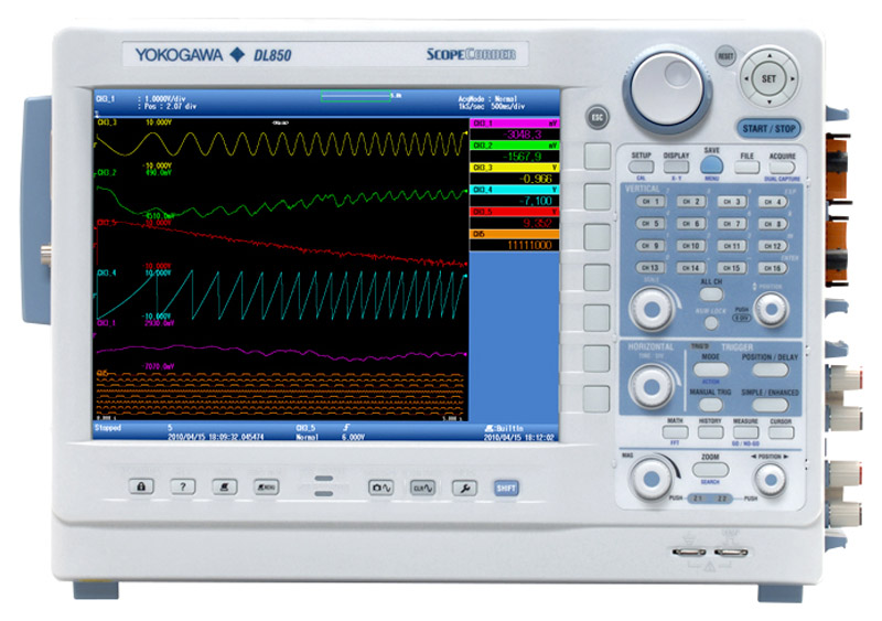
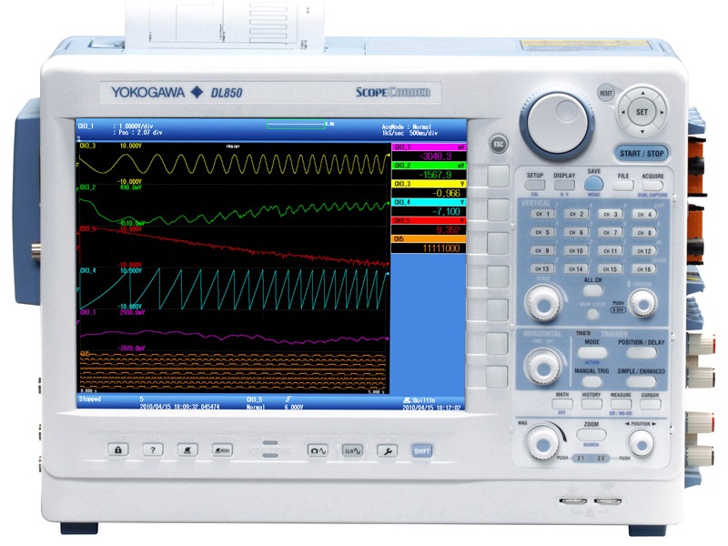


The DL850 ScopeCorder Series are modular, waveform recording instruments that can measure voltage, current, strain, acceleration, and other phenomena-- simultaneously. With high speed sampling, high isolation withstand voltage, and multichannel measurements, the DL850 Series offers powerful support in the evaluation of electromechanical waveforms.
Introducing Our Ultra-Fast Memory Recorder
- High-speed (up to 100 MS/s), High Resolution (up to 16-bit), Isolated (up to 1kV*1)
- Multi-channel, up to 128 Voltage/Temperature or 128 logic bits
- Continuous hard disk recording at 100 kS/s simultaneously on 16 channels*2
- CAN and LIN buses monitoring and trend waveform display (DL850V only)
- 17 plug-in modules
*1. With the isolated probe (700929 or 701947)
*2. With the /HD0 or /HD1 option
The DL850 ScopeCorder Series are modular, waveform recording instruments that can measure voltage, current, strain, acceleration, and other phenomena-- simultaneously. With high speed sampling, high isolation withstand voltage, and multichannel measurements, the DL850 Series offers powerful support in the development, evaluation, and quality control of energy efficient devices.
For increasingly fast inverter signals
High speed (100 MS/s), High resolution (12-bit), 1kV isolated measurements.*
Yokogawa's isoPRO technology offers industry-leading isolation performance at the highest speeds. The isoPRO core technology is designed with energy savings applications in mind. It gives you the performance needed to develop high efficiency inverters, which employ high voltages, large currents, and high operating speeds.
Example - Measuring Inverter Output
 Accurately observe inverter startup waveforms with sufficient time resolution. You can confirm that no excessive overshoots occured.
 |
High Speed & High Withstand Voltage Isolation Technology | |
 |
Using high speed optical fiber-based transmissions, the module achieves high speed ADC clock and data isolation. 720210 High-speed 100 MS/s 12-Bit Isolation Module(Max. four(4) modules can be installed in a main unit.) |
 |
|
Rising waveform not completely captured
|
Rising waveform accurately captured
|


Example: Same inverter output waveform measured at 10MS/s and 100 MS/s
17 plug-in modules allow for flexible assorted measurements.
The lineup includes two new module types: A 16-CH Temp./Voltage Input Module, and a CAN & LIN Bus Monitor Module (DL850V only). All DL850 modules can be combined with measurement modules from the DL750 series products:

|
|
Note: The firmware version 2.00 or later is required when using the 16-CH Temp./Voltage Input Module(720221) and/or CAN&LIN Bus Monitor Module(720241).
Advanced - Even More Measurement Points - Up to 128 CH of voltage input and 128 bits of logic input
The 16-CH Voltage Input Module (scanner type*) can measure at 10 kS/s sample rate even when using all 16 channels. With this module populating all 8 input module slots, the DL850 performs 128-CH voltage measurements.
The Logic Input Module supports everything from TTL levels, to high voltage contact closures at up to 10 MS/s*. With eight logic modules, the DL850 can monitor and capture 128 bits of logic.
Example: Measuring the startup sequence of a multi-output power source
Power supplies used in home computing electronics have many outputs, and it is necessary to control the sequences from output to output. With a multichannel module, you are not limited to voltage measurements; a single unit can also measure everything from PC control signals to AC fan operation, individual component temperatures, and slow to high-speed signals.
 |
Ch 1: AC Input Voltage Ch 6: Supply Voltage Ch 2: Reference Voltage Ch 3: Reset Signal  Ch 1: Fan Rotation 16-bit logic: Control Signals 4-bit logic: Serial Communication
|
 |
Catch transients in durability with high-speed sampling - Dual Capture
To visualize long term trends in durability testing and other situations, data is typically acquired at low-speed sample rates. On the other hand, suddenly-occurring transitional phenomena should be captured at high-speed sample rates.
The "Dual Capture" feature resolves these conflicting requirements by recording at two different sampling rates.
-
Zoom Waveform - You can record up to 5,000 phenomena of high speed trigger measurements (up to 100 MS/s) at a record length of 5-500 kPoints while taking trend measurements at up to 100 kS/s.
- Event Waveform -Displays the timing at which high speed "sub" waveforms are acquired
- Low Speed Main Waveform - Max: 100 kS/s Trend waveform displayed in a low-speed Roll mode
- Capture Waveform - Max 100 MS/s Capture transients with high speed trigger measurement


Example: Parts Durability Testing
Parts used in automobiles and other transportation vehicles must be highly reliable. The "Dual Capture" function is very effective when performing vibration testing of connectors under varying temperatures.
- Chattering is accurately captured at high-speed sampling
- Check the frequency of occurence at low-speed sampling
Recall Past Waveforms - History Function
When you spot an abnormal phenomenon during repetitive high speed measurements, often the anomaly has disappeared from the screen by the time you press Stop.
Always active, the "History" function automatically divides the long memory into up to 5,000 "history waveforms" that can be redisplayed at any time.

To extract abnormal waveforms
|
 |
Searching history waveforms
When you want to extract abnormal phenomena exclusively, you can perform condition-based searches of the history waveforms. You can create a rectangular zone on screen and extract only waveforms that pass through or do not pass through the zone. You can also extract data based on amplitude and other parameters.
To check the history... |
You can display all past waveforms, and view a list of acquisition times at min 1µs resolution |
| Key Point The History function requires no action during measurement. You can recall data at any time after measurement has been completed. Once waveforms have been recalled, you can zoom locations of interest or perform parameter measurements. |
Armed with an array of trigger functions
Simple & Enhanced Triggers
The DL offers easy-to-use "Simple" triggers, or lets you combine various "Enhanced" triggers for even more advanced capturing.
Enhanced trigger conditions are set up intuitively in advanced, easy-to-understand graphical user interface

- Edge: Trigger on a single trigger source condition (rising, falling, rising/falling)
- Time: Trigger at a specified time or fixed interval
Enchanced
- A -> B(N): Trigger when condition B is true N times after condition A becomes true
- A Delay B: After condition A becomes true, trigger the first time condition B becomes true after a set time has passed
- Edge On A: Trigger on an OR condition of an edge trigger while the A trigger is true.
- OR: Trigger if at least one trigger condition of multiple trigger sources is true
- AND: Trigger if all trigger conditions of multiple trigger sources are true
- Period: Trigger when a condition regarding the waveform period becomes true
- Pulse Width: Trigger on a condition relating a pulse width condition being true with a specified time width condition.
- Wave Window: Trigger when the signal passes outside of an real time template "Wave Window"
Example:"A Delay B" trigger setup screen (GUI)
Wave Window Trigger
The Wave Window trigger is useful for diagnosing typical power supply troubles such as momentary loss, sags, and surges. It can also detect frequency changes, voltage drops, and other phenomena, with support for AC waveforms of 40 to 1,000 Hz. A reference waveform (Real time template) is compared with the current waveform, and a trigger activates if the current waveform falls outside of the allowable range. The reference waveform is generated automatically from the previous waveform in real time.
|
*The Wave Window is not displayed on the display. |

Action ON Trigger
To capture infrequently occurring phenomena, you can use an "Action ON Trigger" to perform multiple actions that are specified in advance when a trigger occurs.
 |
You can specify "e-mail transmission" for immediate notification in a remote location when a phenomenon occurs. |
|
|
Superior Noise Rejection
 Excellent noise rejection performance is achieved through meticulous low-noise design. Floating voltage switching waveforms in inverter circuits can also be captured with precision.
 |
Example: Measuring inverter gate signals |

Model 701250 Voltage Input Module
|
Processes Noise Rejection and Executes Power Computations in Real Time - Realtime Math (/G3 option)
The DL850 is armed with a dedicated DSP (digital signal processor) for computations that enables between-channel math during waveform capture. These between-channel computations are powerful because they can be set up separately from fi lter computations. In addition to FIR, IIR, Gauss, and moving average digital fi lters, you can use maximum 35 equations such as arithmetic with coefficients, integrals and differentials, and higher-order equations.
- Display any combination of measured and math waveforms (up to 16 total).
- You can assign channels without modules.
| Example: 3-Phase Power Computation | |
| Power is calculated as the integral of the product of voltage and current over time (an average based on the period). Using the Realtime Math function, you can display 3-phase 4-wire power waveforms in real time. |  |

| Key Point Computations occur in real time even when in Roll mode. Computed waveforms can also be used to activate triggers. Any vacant slots (CHs) can be utilized for the realtime math defi nition. Consequently, precomputation waveform and postcomputation waveform can be displyed simultaneously. |
A wealth of functions gets you right to the waveform you want - User Defined Computation (/G2 option)
The DL comes standard with arithmetic, time shift, FFT, and other computations that enable you to display waveforms with offsets and skew corrections. And with user defi ned computations (/G2 option), you can create equations using a combination of differentials and integrals, digital fi lters, and a wealth of other functions.
User Defined Computation Setup Screen

| Example: Amplitude Analysis Using FFT | |
| With the User Defi ned Computation function(option) included, you can perform various-types of FFT analysis using two FFT windows. In applications such as vibration and shock tests, you can easily evaluate abnormal vibrations while simultaneously measuring other signals. |  |
| Key Point You can assign a log scale to the frequency axis. |
Automatically extract waveform amplitude, frequency, and other parameters - Waveform parameter and statistical computation
Extract and display up to 32 parameters (amplitude, frequency, etc. including delay) simultaneously. Menus can be shown as lists of easy-to-read icons.
| Statistical Computation | |
| The DL can automatically extract cycle waveforms and find the standard deviation and other statistics. Computations can be performed on history waveforms as well. |  |
Detect Abnormal Waveforms, Notify Users, and Determine Pass/Fail - Go/NO-GO Determination
The DL can determine whether waveforms or computed values of waveform parameters meet (GO) or do not meet (NO-GO) conditions that are specifi ed in advance. Upon judgment of the measured results, a pre-set action is performed and users are notified that an abnormal waveform was observed, along with the pass/fail
determination. This is a very useful function for such things as studying signals from manufacturing lines of electronic devices and tracing abnormal phenomena.
| Example: Evaluating Motor Startup Characteristics | |
 |
Parameter measurement is taken of the time until reaching a reference RPM after motor start, and the subsequent GO/NO-GO (pass/fail) determination is made. |
Synchronize Multiple Units Performing Simultaneous Measurements - IRIG input (/C20 option)
 |
Synchronized measurement across multiple DL850 units is made possible by inputting an IRIG time code signal.* The DL850/ DL850V's internal clock is also synchronized (locked) to the IRIG signal. Therefore, timing comparisons are highly precise even when continuously recording over long periods of time. |
| Key Point You can make periodic observations remotely by connecting commercially available GPS receivers that have IRIG output and using the Time Trigger function. |
Example: Synchronous measurements for large transport vehicles Simultaneously measuring both tips of airplane wings, or between railroad cars requires synchronizing multiple measuring instruments in time. With a single IRIG cable, the acquisition time of all data is made the same.

*IRIG (Inter-Range Instrumentation Group) started as an American military standard, and is now used in data recorders in the aerospace industry. The carrier frequency is a 1 kHz/10 kHz ASK (amplitude shift keying) modulating signal with a synchronizing precision of as high as 1 µs. DL850 support formats: A002, B002, A132, B122
The Flexibility of an External Hard Drive - External Hard Drive Interface (/HD0 option)
| With an external hard drive interface, you can connect a commercially available eSATA standard hard drive. The DL can record to an external drive in real time just like it can with the built-in hard drive. After saving waveforms, you can switch the DL850/DL850V from the PC to the external drive and use the waveform data immediately. |  |
Key Point
* The speed of realtime hard drive saving depends on the performance of the hard drive. |
Check the Relationship between Hysteresis and Phase - XY Display Function
You can confirm the relationship between two signals using the X-Y display. This can be applied to measurements such as the phase angle of two sine waves.
You can select four combinations on the X and Y axes, and therefore display multiple X-Y waveforms simultaneously and find relationships between them.
Simultaneous observation of X-Y waveforms and normal T-Y waveforms (waveform display using voltage and time axes) is also possible.
Example: Computing dynamic BH characteristics of a magnetic substance On the DL850 you can measure voltage and current, then analyze hysteresis of magnetic flux density B and magnetic field strength H. Energy loss generated by magnetostriction can be evaluated by measuring dynamic BH characteristics.

Magnetic flux density: B = Integ (C1) / (K1*K2)
Magnetic field strength: H = C2*K1 / K3
C1: voltage, C2: current
K1: number of turns, K2: cross sectional area
K3: magnetic circuit length
Snapshots
With the push of "SNAP SHOT" key, you can save a "snapshot" of the measured waveform (the waveform displayed on screen). The waveform remains saved even if you restart measurement, therefore you can easily compare the snapshot with any newly measured waveforms. Snapshots can also be saved and loaded as files.
 You can compare waveforms from varied conditions |
Example: Comparison of a snapshot waveform (white) with another waveform |
Web Server
 You can operate controls and acquire screen images with a Web browser - no special software required on the PC. |
The Web Server function displays the screen of any networked DL850/DL850V on a PC via Ethernet. From this screen, you can remotely start or stop measurement, update the DL's display, and take snapshots (capture images) of the screens. |
Multilanguage Support
|
Adhesive front panel key label sheets ("panel sheets") are available in eight different languages. Multilanguage support is also provided for menus and error messages. |
Saving Screen Images and Displaying Thumbnails
 Screen images saved to storage media are shown on screen as thumbnails for easy identification. |
Screen images can be saved to a specifi ed storage medium in PNG, JPEG, or BMP format. These screen images can be imported into reports or other PC-created documents. |
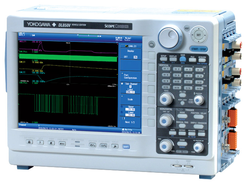
Enhanced capabilities for vehicle design and development such as CAN & LIN Buses monitoring

The DL850V ScopeCorder Vehicle Edition can display CAN- and/or LIN-protocol communication data as trend waveforms on the display by using the CAN Bus Monitor Module (720240) or CAN & LIN Bus Monitor Module (720241(*1) ). It can also trigger on decoded waveforms. By identifying the correlation between communication data on the vehicle-installed LAN and analog data such as voltage, temperature, and sensor signals or the ECU’s control logic signal, a vehicle’s overall LAN system can be evaluated. Furthermore, with the /DC option, the DL850V can be driven by DC power such as the vehicle’s battery, in addition to ordinary AC power.
(*1): The CAN & LIN Bus Monitor Module (model: 720241) is supported by the main unit firmware ver. 2.00 or later.
Utilization of Vehicle-installed Network Definition Files (CAN DBC, LIN LDF)
Data to be acquired using a bus monitor module (720240 or 720241) can be specified not only in digital code (hexadecimal or numeric), but also loaded from a network definition file (CAN DBC or LIN LDF).

| Example of comparison and verification of a measured signal and CAN bus signal You can trend the physical value of CAN bus data and the corresponding measured waveforms on the same screen at once. For example, an ignition switch ON/OFF signal, a CAN signal corresponding to that command, and an actual signal measured by a pressure sensor, etc. can be displayed and checked on the same screen, to verify the correlation of those signals. |
|
|


Support for both AC and DC power (/DC option, DL850V only)
- Low power consumption of 60 - 120 VA (typ.)
- Low noise
The DL850V Vehicle Edition can be driven by a 12 V DC battery, vehicle’s cigarette lighter, or ordinary AC power. (We provide accessories for DC driving; see the list of accessories at the end of the catalog.)


Photo: DL850V/DC option model
- EXT I/O - GO/NO-GO determinations can be output, and you can perform control based on start/stop and other external signals
- External clock I/O (EXT CLK IN) - Perform sampling timed to an external signal (up to 9.5 MHz).
- External Trigger Input (EXT TRIG IN)
- External Trigger Output (EXT TRIG OUT)
- Video signal output (VIDEO OUT) - Confirm waveforms on an analog RGB (XGA) external display.
- USB-PC Connection Terminal - Enables control from a PC.
- Ethernet 1000BASE-T - Comes standard
- GP-IB (optional)
- IRIG (optional*2) - Inputting an external time signal lets you synchronize multiple DL850s.
- External hard drive IF (optional*1) - Connect an eSATA standard hard drive.
- SD Card Slot - SD, SDHC compliant, comes standard
- USB Peripheral Connection Terminals - Supports USB storage, keyboards, and mouse input.
*1 Built in hard disk and external hard disk IF are not available together.
*2 The GP_IB is also available when IRIG (/C20) option is specified.


There are several factors for a user to consider when using an IEPE accelerometer, particularly when used with newly available integrated signal conditioner/data acquisition process. Correctly managing these factors will help the user avoid erroneous data from their IEPE accelerometer and ensure the quality of the data measurement is at the level they expect and require.

With the increased demand in electric-hybrid vehicles, the electromechanical designs of in-vehicle systems are becoming more sophisticated and there has been a demand shift towards high efficiency brushless direct current motor (BLDC) implementation. Think of motorized seat adjustment, electric window, power steering, HVAC fans, pumps, etc. In many of these systems various types of motors are used as actuators; more specifically, 3-phase BLDC motors are gaining popularity as they provide these important advantages:
- Improved speed vs torque characteristics
- High dynamic response
- High efficiency
- Extended speed ranges
- Long operation life

With increased focus on reducing energy consumption and compliance with efficiency standards, this app note provides an overview on the types of measurements needed for efficiency and power quality, and the instruments that take them.

Designing an instrumentation system for high current measurement requires careful consideration of the trade-offs associated with each type of sensing device. The purpose of this application note is to help engineers understand the sensing choices available and the corresponding trade-offs with each technology.

The objective of this paper is to show the close relationship between efficiency and power quality, and provide education on the causes of power quality, types of power quality issues, and provide guidance on measurement considerations.


- Yokogawa DL850 ScopeCorder PP Compression setting
- PP Compression as post-process within Xviewer

As a respected pioneer in folding bikes, Brompton’s first foldable e-bikes was eagerly anticipated. However, to develop such high-performance e-bikes engineers at Brompton needed to perform comprehensive dynamic testing to achieve rider – bike harmony.

In a research published in the SAE International Journal of Fuels and Lubricants, researchers from Georgia Southern University use a Yokogawa Test&Measurement DL850 ScopeCorder to record and monitor data from a piezoelectric pressure transducer in-cylinder, a pressure sensor for intake pressure, and an optical rotary encoder for engine rotational position and speed, and to test the combustion and emissions characteristics on an experimental engine.

In this research paper published by the Department of Mechanical Engineering at Georgia Southern University, researchers use a Yokogawa Test&Measurement DL850 ScopeCorder for real-time high-speed data acquisition on a research engine to investigate the low-temperature combustion regions of aerospace F24 and ULSD for emission reduction.
Instruction Manuals
- DL850E/DL850EV ScopeCorder Features Guide (14.0 MB)
- DL850E/DL850EV ScopeCorder User's Manual (8.8 MB)
- DL850E/DL850EV ScopeCorder Getting Started Guide (14.0 MB)
- DL850E/DL850EV ScopeCorder Communication Interface User's Manual (4.3 MB)
- DL850E/DL850EV ScopeCorder Real Time Math (/G3)/Power Math (/G5) User's Manual (4.8 MB)
- Precaution Concerning the Modules (178 KB)
- Model 701990 Sample Program for the DL Series Digital OscilloscopeRead this first. (193 KB)
- Combustion Pressure Analysis Software (For Gas) (1.9 MB)
- Combustion Pressure Analysis Software (For Gasoline) (1.8 MB)
- Combustion Pressure Analysis Software (For Diesel) (2.0 MB)
- Please Read before Installation (Combustion Pressure Analysis Software) (756 KB)
Software
- Xviewer 701992 / XviewerLITE
- Xwirepuller
- Symbol Editor
- DL-Term
- Binary Data File Converter
- Communication Sample Programs
- DL850/DL850V WDF File Access Library
- TMCTL
- USB Drivers
- LabVIEW drivers for DL850 series ( NATIONAL INSTRUMENTS Web Page )
- Yokogawa WDF DataPlugin ( NATIONAL INSTRUMENTS Web Page )
Firmware
Webinars
- Establishing baselines for system efficiency
- Conducting inverter control signal analysis at the systems level
- Identifying critical measurements for benchmarking inverter input, inverter output, and motor output
- Analyzing motor control signals, including torque control variables, positional sensors, and pulse-width modulation (PWM), as well as torque measurements
- How to avoid the “gotcha's” of inverter-based measurements
- Computations for field-oriented control
- The integration of CAN bus communications
- Correlations in the frequency domain
- Other advanced motor and drive topics

With ongoing innovations in motor and inverter technologies seeking to advance global decarbonization objectives in the automotive industry, it’s crucial that engineers have a thorough understanding of how to properly analyze these systems.
This complimentary webinar provides engineering professionals involved in motor and control system development with insights that enable data benchmarking and troubleshooting issues related to energy efficiency in electric vehicle (EV) powertrains.
Key webinar topics include:

You know the basics of electrical power measurements, have set up your dyno, and made key measurements – which is great. But as your motor and drive projects progress, the complexities of system drive requirements can change frequently. Control algorithms, networked communications, and mechanical systems form a complex web of interactions that need sorting. This 60-minute webinar explains how to get past ground-level measurements and delve into comprehensive solutions that leverage test and measurement instruments including power analyzers, high-speed data acquisition, and real-time software.
Topics include:
The technical presentation includes an audience Q&A.