An integrated measurement system for every electromechanical application
Faced with complex integrated systems, engineers need a sophisticated, flexible measurement solution for R&D, validation, and troubleshooting. ScopeCorders meet this challenge with built-in analysis and recording functions in an all-in-one data acquisition solution.
Designed for engineering insights, Yokogawa Test&Measurement ScopeCorders are:
- Integrated: Automate your measurements and analysis by making menu selections - no programming required.
- Configurable: Simultaneously capture data from any of 20 different modules.
- High Fidelity: Trustworthy measurements even in the noisiest environments.
To request a quote for the DL350 Portable ScopeCorder, the DL950 ScopeCorder, the SL1000 High-Channel Count ScopeCorder, or the IS8000 Integrated Test and Measurement Software Platform from Yokogawa Test&Measurement, click the LiveChat button on the side of the page or submit an inquiry via our Contact Us page.
"I owe my career to T&M"
It’s not an exaggeration to say I owe a good bit of my career success to Yokogawa Test&Measurement. By using their ScopeCorders that combine the best parts of an oscilloscope and DAQ, projects that once took weeks across multiple instruments suddenly only took a few hours with just one instrument. The impact on what I could accomplish really was quite remarkable, and my ability to accurately complete projects in record time made me look incredible. No matter how complex or convoluted the task, the ScopeCorders never fail to easily handle anything I throw at them. They’re amazing instruments and I tell others about them every chance I get.
—Kenneth Shoemaker
Automotive Industry Consultant/Owner at Panama Prototypes
Automotive Industry Consultant/Owner at Panama Prototypes
10+1 Reasons to Choose a Yokogawa ScopeCorder
Application Note
Whether the measurement signals are derived from the smallest electric drives incorporated in a precision watch, a large turbine found in a power generating facility, sensors and electronics found in a modern electric vehicle, or from household appliances, the features and flexibility that come with the ScopeCorder offer value to all these applications.
This application note discusses the top 10 reasons, plus one, to select a Yokogawa ScopeCorder.
Read the App Note

The Yokogawa Test&Measurement DL950 ScopeCorder captures and analyzes a wide variety of electrical, physical sensor signals, and serial buses. It offers a unique combination of high sampling rates, for a detailed view and long recording times to monitor trends over time.

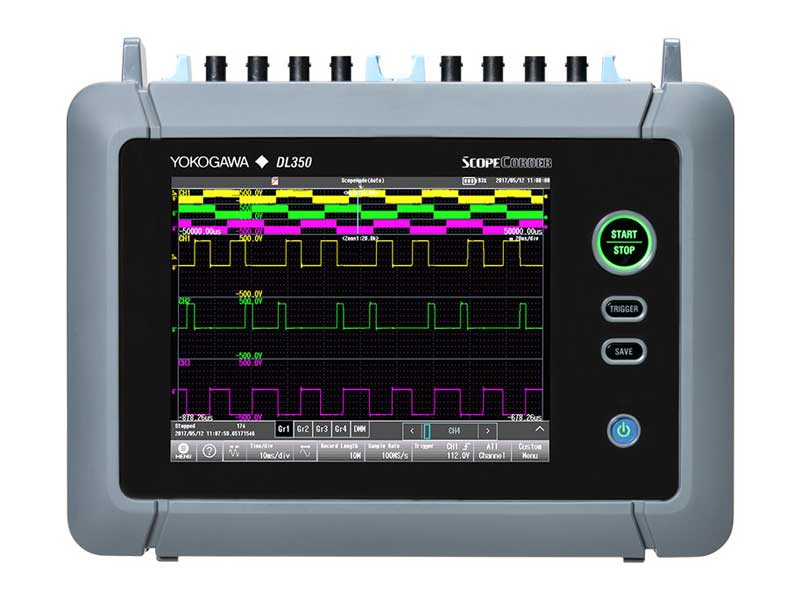
A compact, battery-powered, touch screen instrument you can take into the field featuring the deep measurement and recording capabilities you need in the lab.
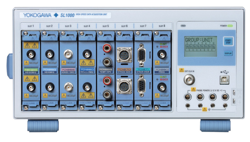
A headless ScopeCorder system capable of connecting multiple chassis into one PC-based system.
- IS8000 comprehensive test and measurement software
- Accelerate engineering workflow
- Integrate timing, control, and data collection from multiple instruments

| DL350 Scopecorder | DL950 Scopecorder | SL1000 High Speed DAQ | |
|---|---|---|---|
 |
 |
 |
|
| Instrument Control | Standalone | Standalone or PC-Based | PC-Based |
| Analog Channels | Max 8 Isolated CH | Max 128 Isolated CH | Max 128 Isolated CH |
| Sampling Rate | Max 100 MSamples/sec | Max 200 MSamples/sec | Max 100 MSamples/sec |
| Vertical Resolution | Max 16 Bits | Max 16 Bits | Max 16 Bits |
| Input Modules | Voltage, Temp, Strain, Accelerometer, Frequency - Supports 18 Modules | Voltage, Temp, Strain, Accelerometer, Frequency - Supports 20+ Modules | Voltage, Temp, Strain, Accelerometer, Frequency - Supports 13 Modules |
| CAN/LIN Bus Input | /VE Option Required | Available | Not Available |
| Trigger Functions | Rise/Fall and Enhanced Scope Settings on all Channels | Rise/Fall and Enhanced Scope Settings on all Channels | Rise/Fall on all Channels |
| Internal Record Length | Max 100 Mpts/Module | Max 4 Gpts/ch | Max 50 Mpts/ch |
| Real-Time Data Streaming | Available to SD Memory Card | Available to PC, Internal SSD, and Flash Acquisition | Available to PC and Internal HDD |
| Real-Time Analysis Functions | Not Available | Real-Time Math and Power Math (/G03, /G05 Option) |
Not Available |
| Touch Screen | Available | Available | Not Available |
| Battery Powered Operation | Optional | Optional | Not Available |

Overview:
Testing actuation of a side impact airbag to measure the optimal timing.
Industries:

Overview:
Measurement guidance related to field-oriented control (FOC) of electric motors with example use cases that illustrates how this is accomplished using a power analyzer and/or a ScopeCorder. Specifically addressed are direct and quadrature currents of a surface-mounted permanent magnet motor (SMPM) with field weakening applied. The techniques illustrated can also be applied to other FOC variables, algorithms, and motor technologies.
Industries:

Overview:
DL950_Comprehensive_evaluation_of_vehicle_systems_using_real_signal
Industries:

Overview:
- DL950
- Evaluating and designing the Electric Power Steering (EPS)
- Multi-channel simultaneous measurement
- Real-time calculation
Industries:

Overview:
A ScopeCorder is a powerful portable data acquisition recorder that combines features of a multi-channel digital oscilloscope and a high-performance oscillographic recorder. As such, it can capture and analyze both short-term transient events and long-term trends for periods up to 200 days.


Overview:
This application note provides guidance for making measurements relating to field-oriented control of electric motors and presents an example use case that illustrates how to accomplish these with the /MT1 option on a Yokogawa Test&Measurement DL950 ScopeCorder. Specifically addressed are direct and quadrature currents of a surface-mounted permanent magnet motor with field weakening applied. The techniques discussed are also applicable to other field-oriented control variables, algorithms, and motor technologies.

Overview:
DL950_Switched_Mode_Power_Supply_Output_Monitoring


Overview:
Using the OR trigger and Dual Capture, it is easy to trap and record failure conditions on electrical harnessses (wiring interconnects) over a long duration test.

Overview:
DL950_Evaluation_of_ECU_and_InverterMotor

Overview:
Designing an instrumentation system for high current measurement requires careful consideration of the trade-offs associated with each type of sensing device. The purpose of this application note is to help engineers understand the sensing choices available and the corresponding trade-offs with each technology.

Industries:

Overview:
Use built-in calculations to analyze motor rotor position of Brushless DC motors (BLDC) and Permanent Magnet Synchronous Machines (PMSM) and find the relative angle between the rotor and position sensors such as encoders or resolvers

Overview:
How can I capture data from motion sensors synchronized with other analog data? The Yokogawa ScopeCorder series of instruments feature input modules and functions to make this possible.

Overview:
- Battery Voltage Fluctuation During ABS Action
- Why Does My Battery Voltage Meter Fluctuate During ABS Action?
Industries:

Overview:
- Construction and verification of SENT communication system
- Accurate, reliable data transmission at low cost
Industries:
Application Note

Overview:
With increased focus on reducing energy consumption and compliance with efficiency standards, this app note provides an overview on the types of measurements needed for efficiency and power quality, and the instruments that take them.

Overview:
Government agencies that define the standardization of energy efficiency metrics continue to be a driving force behind the development of the next generation electric vehicle powertrains. These metrics require manufacturers to have high confidence in their measurements and motivate the optimization of efficiency.
Industries:

Overview:
- Motor testing, variable speed drive testing procedure
- AC, DC, and power measurement
- Precision measurements on motors and VFD systems
- How to calculate energy efficiency

Overview:
- Yokogawa DL850E ScopeCorder
- Waveform measuring and recording instrument
- Eight slots for signal conditioning, data acquisition module
- Signal inputs up to 100 MHz sampling rate
Industries:

Overview:
Standards driving energy efficiency classifications are a driving force behind the development of the next generation of motor and drive technologies. Learn more here.
Industries:


Industries:

Overview:
The objective of this paper is to show the close relationship between efficiency and power quality, and provide education on the causes of power quality, types of power quality issues, and provide guidance on measurement considerations.
Overview:
The maximum external HDD size is 1.5 TB.
Overview:
The 702911 and 702912 Logic Probes cannot be used with the DL750/DL750P. The logic probes were orginally designed to be used with the OR Series. The SL1400 can use the 700986, 700987, 702911, 702912. The DL750 can ...
Overview:
- How Do I Set the Sample Rate on my DL850/DL850V ScopeCorder to XYZ Samples/Second?
- Use attached "Sampling Rate Table.xls" to help determine appropriate Record Length and Time/Div setting...
FAQ

Overview:
The /HD0 External HDD Interface and /HD1 Internal HDD options cannot be installed on the same instrument. When the internal HDD reaches capacity, it must transfer files to the PC to clear space before saving the next ...
Overview:
- We have tested the following IRIG generator for compatibility with the DL850
- GPS200
- ES101
Overview:
Unfortunately, it does not work for the files created on a DL750 ScopeCorder. It is a dedicated feature available only for the DL850/DL850V ScopeCorder.
Overview:
Whether you are new to the DL850/DL850V ScopeCorder or it's been awhile since you last operated the instrument, the DL850 Self-Paced Student Workbook is a great getting started guide. It contains 18 step-by-step ...
Overview:
- 720268 High Voltage Module maximum input voltage derating analysis curve
- DL850E/DL850EV ScopeCorder
Overview:
- C/C++ and Visual Basic Sample programs for controlling the DL850/DL850V
- Latest visual basics /C++ sample programs from the Software Downloads available on y-Link
- Visual basics for portable data acquisition
Overview:
- In most cases, all DL750 ScopeCorder modules will be compatible with DL850 ScopeCorder and SL1000 High Count ScopeCorder.
- But some modules can be used with DL750 ScopeCorder that cannot be used with DL850 ScopeCorder.
Overview:
Unfortunately, the DL850 ScopeCorder is neither IVI nor LXI compliant and there are no drivers for either standards.
Overview:
If during the DL850/DL850 ScopeCorder firmware upgrade process, the display screen turns black, blue, or something in between and the installation failed, please complete the following steps. You will need a USB printer cable to ...
Overview:
The DL850/DL850V ScopeCorder cannot be set to 100ns/div when the following modules are installed: 720240 CAN Bus Monitoring Module 720220 16 Channel Voltage Input Module Removing these modules permits the DL850/DL850V to be ...
Overview:
The lowest, guaranteed operating temperature covered under warranty is 5°C. The lowest, guaranteed storage temperature covered under warranty is -20°C.Unfortunately, we have no practical way of determining which ...
Overview:
The largest flash drive size that can be detected by the DL850 ScopeCorder is 16 GB. The largest external hard drive size that can be detected by the DL850 is 1.5 TB.
Overview:
To determine the start and end point of the zoom box for DL850 ScopeCorder, issue the following commands: :WAVEFORM:START :WAVEFORM:END :ZOOM:POSITION? :ZOOM:MAG? :ZOOM:POSITION1? :ZOOM:MAG1? :WAVEFORM:LENGTH? You can then calculate the ...
Overview:
Please download and view the attached QIS document for detailed calibration procedures for the 720240 CAN bus monitor module. In addition, the "720240 Settings.doc" has step-by-step screenshots on the settings you will ...
Overview:
In terms of display resolution, the 720210 and 701250 modules (12-bit) are equivalent to a 4 digit DMM. The 701262 module (16-bit) is equivalent to a 5 digit DMM. However, in terms of DC accuracy, the 720210 and 701250 ...
Overview:
If you discover that your waveform data/trace or some channels have disappeared from the ScopeCorder DL850/DL850V or Xviewer when you re-load the WDF data file, this is normal behaviour due to an incomplete acquisition. For ...
Overview:
- DMM Data Logger issue
- Connecting DL850 ScopeCorder to IRIG
Overview:
No, it is not possible to use the WDF File Access API in LabView to read *.WDF files. Although LabVIEW can use and access DLLs, there is a special function in the WDF File Access API called WdfGetSacleWave64, which ...
Overview:
The formula for calculating the file size for a Binary type (with *.WDF extension) is: File Size = 805kB + (DataLength*ChannelCount*HistoryCount*2) where 805kB is the ...
Overview:
No, MATLAB cannot use the WDF File Access API to read *.WDF files.There is a special function in the WDF File Access API called WdfGetSacleWave64, which is used to read the data from the *.WDF file. This command uses ...
Overview:
- 720211 High-Speed 100 M/s, 12-Bit Isolation Module vs 720210 Analog Voltage Input Module
- You can only use four 720210 modules per DL850E
- You can use up to eight 720211 modules
Overview:
This method will not work as the signal waveform would be very distorted. The coax acts as a heavy shunt-capacitance at the 'output' jack of the passive probe circuit. As a result, this excessive shunt-capacitance ...
Overview:
Unfortunately it is not possible to convert a .WVF file to a .WDF file. A .WVF file saved by a DL750 can only be loaded in Xviewer or a DL750. Xviewer is capable of loading both .WVF and .WDF file formats.
Overview:
No, if you send commands simultaneously from another communications interface, that has not been selected on the DL850/DL850V, the instrument will not execute the commands properly.
Overview:
If the files saved on the DL850 ScopeCorder do not appear on the PC, please disconnect and reconnect the USB connection from the DL850 to the PC.This behavior is normal for Windows based operating systems including Windows XP, ...
Overview:
The measured output response time of the 701260 Analog Voltage Input Module, when observing RMS is: Rising (0 to 90% of 10 div): 100ms Falling (100 to 10% of 10 div): 250ms An attached JPEG displays the results of ...
FAQ
Overview:
There are some modules that can be used with the DL750 Scopecorder but cannot be used with the DL850 Scopecorder. This is due to the nature of the FPGA for that module, which cannot be interchanged between the DL750 Scopecorder and the DL850 Scopecorder. During ...
Overview:
The AC Power Input in all Yokogawa instruments is designed as a 3-pin connection (one of which is a GND pin). In some parts of the world, PCs are sold with AC power cables that are 2-pin. Often times this means the ...
Overview:
The SL1000 High-Speed Data Acquisition Unit Portable Parallel Analyzer (PPA) doesn’t support offset summing like DLM2000 Mixed Signal Oscilloscopes. The SL1000 doesn't have offset hardware; instead, the vOffset variable is used to affect the displayed value only. So, using this parameter would have no ...
Overview:
The SL1000 High-Speed Data Acquisition Unit has the following types of memory: Internal Hard Drive: 40 GB Non-Volatile SRAM Waveform Acquisition Memory: 128 MW or 256 MB Volatile RAM Setup File Data Storage: 1 MB Volatile SRAM(Battery-Backup)
Overview:
When making a WT230 Digital Power Meter RS232C connection using GateWT, please verify the following RS232C communication settings on the instrument: Mode = 488.2 Hand = 0 For = 0 Baud Rate = 9600 Terminator Cr+Lf Even though you can run ...
FAQ
Overview:
- Lowest possible device setting for sample rate on Yokogawa DL850 ScopeCorder is 5 Sa/sec
- Methods for much lower sample rates
- External clock, etc.
Overview:
The DL series instruments are capable of measuring the delay between traces or the delay between channels. The measured output value can be displayed in either time or degree. To setup the DL850 Scopecorder to measure delay, follow ...
Overview:
Decimation is a technique used to reduce the total number of samples. You can use Xviewer to perform decimation on your waveform data files that have the WDF/WVF/ASCII CSV extension format. Decimation reduces the ...
Overview:
We do not have an instruction manual describing the *.WDF file format structure like we did for the *.WVF files.
We provide a list of support options with more details.
Overview:
If your DL series oscilloscope is not measuring rise or fall time, it may be because you are attempting to measure asymmetric waveforms. It is not possible to perform automatic rise or fall time measurements on DL ...
Overview:
High Resolution mode can be used to remove high frequency noise and increase vertical resolution. It achieves this by increasing the number of effective bits per data to 12-bits through digital and bandwidth filters.
Overview:
- Unbalanced input, balanced input, isolated input, and differential input
- Types of inputs guide presentation
- Related products and solutions
Overview:
- Yokogawa DL850 ScopeCorder PP Compression setting
- PP Compression as post-process within Xviewer
FAQ
Overview:
Unfortunately we do not have any experience using the SL1000 Acquisition Software on a PC that has Symantec Endpoint Encryption Software (SEES) installed.
SEES is a storage encryption software that provides data ...
Overview:
- Correct AC coupling test for the 720210 Analog Voltage input module must be performed at 20 Hz
- Service manual SMDL850-01EN_010 1st Ed suggests performing AC COUPLING test at 15 Hz
- This is a typo
Overview:
Microsoft(R) Excel 97 and 2000 only.
Overview:
To use the waveform parameter Measure function or the computation Math function, you need the 707702 Computation Function Setup Software. In the case of the WE7111 Digital Oscilloscope Module, you can perform waveform parameter automatic ...
Overview:
If you are using serial communication or ethernet to connect the WE7000 Control Software to the PC, it is necessary to create a shortcut with a start option added to the end of the shortcut target. For WE control ...
Overview:
In free run mode, the execution timing is different depending on the type of computation. In the case of computations such as FFT, Filter, pulse width, etc. various data are arranged in a chronological direction.
Overview:
The Time Axis Accuracy is the accuracy of the A/D clock. It is not possible to directly measure the A/D clock and the A/D clock is not output from the ScopeCorder DL850/SL1400. To verify the accuracy of the A/D clock, you will ...
Overview:
Question:If the DL9000 Oscilloscopes is in normal trigger mode and no waveform acquisitions have been made i.e. the scope has not triggered, a query to the instrument using the :Waveform:Record or :History:Record? Minimum it returns ...
Overview:
Frequency to Voltage Conversion Problem: A transducer produces a sine-wave output dependant on the voltage-input; here is how to decode that output with a scope or a ScopeCorder. For 3kV input, the transducer ...
Overview:
The DL850 can be installed with one of the following language options:JapaneseEnglishChineseKoreanGermanFrenchItalianSpanishRussianFor the English (-HE) model, the menu and message language can be changed in the UTLITY ...
Overview:
The free software DL-GATE can be used for the following products only:DL1700E seriesDL7400 series (firmware version after 1.32)DL1600 series (firmware version after 1.13)DL750 series (firmware version after ...
Overview:
How to use SNTP on DL850 ScopeCorder The sequence below is very important for SNTP to work properly.1. Set DATE/TIME and GMT Time Difference to your location FIRST. EDT is -4 hours, EDT is -5 hours - as examples. 2. Set a SNTP ...
Overview:
The sanitation procedure for various Yokogawa oscilloscopes have been documented below. Please download the document or pdf that refers to your Yokogawa oscilloscope.
Overview:
No, the SL1000 and 720210 Modules service manual does not include any adjustment procedures however, it does contain the inspection procedure (QIS).
Overview:
To perform a shunt calibration using the 701271 strain gage module and the ScopeCorder, please complete the following procedures: Connect the strain module 701271, bridge head 701957/701958 and the strain ...
Overview:
The maximum total file size you can record continuously depends on your sample rate, channel count and storage capacity. Please see the attached PDF file for an example of recording settings.Note: The dead-time between ...
Overview:
The SL1000 is capable of transferring previous data sets/files while streaming is still in progress through the File Divide feature. When the SL1000 starts recording, it opens a new file and starts logging data. If the ...
Overview:
Depending on the mode, the dead time may range from 0 to 10ms approximately. The dead time for the different modes are listed below. Free Run Mode: 0ms Normal Mode without HDD recording: 10ms Normal Mode with HDD ...
Overview:
Yes, VXI-11 is required and needs to be enabled for the DLM2000 Mixed Signal Oscilloscope to connect properly to Xviewer when using an ethernet connection. If the VXI-11 option is unchecked, a connection failed message will appear. Related ...
Overview:
One possible solution is to use a third party 10:1 attenuator such as the one shown in the attached document. You may use the attenuator to allow the direct input of higher voltage levels with the 701262 module, since ...
Overview:
The SL1000 High-Speed Data Acquisition Unit is capable of linking up to 8 units, up to 128ch max, in synchronized mode using our SL1000 Acquisition Software. Using a common LINK file, data from all units can be processed and analyzed, as one, at the ...
Overview:
Xviewer may only be used to view and analyze data saved by the SL1000, it cannot be used to remotely control the SL1000. You can also transfer files between the SL1000 and a PC. For the SL1000, Xviewer can support ...
Overview:
Please see the attached document.
Overview:
Yes you can load the setup files *.WES that was saved using the older version of the WE Control Software onto the newer version of the WE Control Software. Please follow the procedures listed in the attached PDF file.
Overview:
- Update Firmware on SL1000 High Channel Count ScopeCorder modular data acquisition system
- Follow instruction procedures
Overview:
- "Beat Method" for Inspecting an Oscilloscope’s Time Base Accuracy
- Inspect and verify time base accuracy
- Aliasing effect to create a "beat waveform."
- Time base setting formula
Overview:
- Xviewer can open multiple files from different DL, SL, and WE series instruments into a single window display
- Same sample rate, trigger position, record length
Overview:
- DC Precision when changing the DC waveform position setting on DL1600
- How to calculate DC offset voltage
Overview:
The Gage Factor setting for the 701271 Strain Input Module can be directly inputted within the range of 1.90 to 2.20. However, it is possible to indirectly set the Gage Factor to a larger value by setting the constant ...
Overview:
You can express any arbitrary exponentiation, in Xviewer or DL series instruments, by using the LOG (common logarithm) and EXP (exponential) functions. For example, for C1 raised to the exponent of 0.2, the math ...
Overview:
- The Offset function vs. the Position function
- Set vertical position of a waveform in voltage value (v)
- Set horizontal location of a waveform in division value (div)
FAQ
Overview:
Even though the correct USB drivers have been installed, and the device displays correctly in the Windows Device Manager Window, the High-Speed Data Acquisition Unit SL1000 Acquisition Software fails to detect the SL1000 main unit. Solutions: Verify ...
Overview:
Yes, you can use the 700929 isolated probe with non-isolated input modules.
Overview:
For the 701280 Frequency Input Module with a 4th order IIR 6Hz lowpass filter, a 60Hz sine wave (FM modulated with a square wave) was measured with deviations of ± 3Hz. Please download and view the attached image for ...

Overview:
The attached file contains an Excel spreadsheet with an API that will query data from the DL850 ScopeCorder via USB, to obtain and display the Time/Div setting. To use the Excel API, follow these procedures: Download and extract ...
Overview:
Xviewer waveform viewer software can calculate various power analysis measurements such as power factor, real power, reactive power, and apparent power. Two sample waveforms are available in the attached zip file, and should be used ...
Overview:
The Delay Measurement value is a Fixed-Point Number.The Delay Measurement feature on the DL850 comes in two modes, Time and Degree. The output of the Delay Measurement feature is a time-based value and not an amplitude ...
Overview:
The DL850 ScopeCorder is capable of linearizing an input signal using the Polynomial Feature in the /G3 Realtime Math option. The polynomial feature performs a fourth order polynomial calculation on the selected source waveform. To ...
Overview:
To set the DL850 ScopeCorder in Roll Mode, turn the Time/Div knob until it is set to 100msec/Div or longer. If the Time/Div is set to 1Hr/Div or longer, waveform scrolling can be difficult to observe in real-time. This is due ...
Overview:
Please make sure you have the latest version of Xviewer installed.
Overview:
The DL850 ScopeCorder G3 Power Measurement option can be used to calculate the power of a Sinusoid-Current Burst. Please download and view image for a screenshot demonstration of the DL850 G3 Power Function.The firmware version of ...
Overview:
- Deskew on DL850 ScopeCorder when using a current probe
- DL850 does have enough resolution to perform deskew
- Will not be able to find the time offset
Overview:
For the DL850 Scopecorder G3 Frequency Function, you will need to set the hysterisis of the edges that are used to detect the periods. This will increase the tolerance for noise and improve measurement reliability.To configure ...
Overview:
Unfortunately Xviewer is not a client-server type software and it is not recommended to run Xviewer on a Windows Server based OS. Xviewer needs to be installed on a client PC to operate without issue. We cannot ...
Overview:
- DL850 can save measured waveform data to a file in Binary, ASCII, or Floating Point format
- Use FILE Waveform Save Menu or SAVE MENU menu
- Learn how to save dual capture files using SAVE MENU
Overview:
Unfortunately there is no way to read these warning messages on the DL750 ScopeCorder. In addition, there is no other command available to determine if there was "No Matching Record" found in History for a particular ZONE ...
Overview:
To determine the exact trigger time of the waveform acquisition, use the ":HISTORY:TIME? 0" command, where 0 refers to the latest acquisition record.To determine the exact trigger sample number, use the ...
Overview:
The new 700929 isolation probe has two new parts: Safety Plug-on clip B9940WX and Safety Clip Lead B8023ZC. The old 700929 isolation probe only has one part, the Pincher Tip B9940WH. Please refer to the attached PDF ...
Overview:
- Download and view attached PowerPoint presentation for comprehensive guide
- How to operate DL850 ScopeCorder Dual Capture mode
Overview:
Error(Code:539)Press ESC Key to Close. Module configuration is not matched, so it couldn’t loaded. Configuration of saved data can see by the File property. The following error is ...
Overview:
On the DL850 Scopecorder, the list starts with #0000 and corresponds to the last triggered waveform captured. The next entry, #0001, corresponds to the first triggered waveform captured and proceeds to list the captured waveforms ...
Overview:
Using the DL850 ScopeCorder, the waveform data was directly saved as an ASCII file in the *.CSV and *.WDF file format (NOT an Xviewer conversion). The sample files that have been provided contain the same waveform data, which is a ...
Overview:
If you wish to view the timestamp data in high resolution, you will need to open the *.CSV file with Notepad or Wordpad. If you use Microsoft Excel to open the file, Excel will round the timestamp data, preventing you ...
Overview:
- Correct syntax for implementing the Atan function on the DL850 scopecorder is ATAN(C1)
- There is a typo in the DL850 IMDL85001EN 4thEd Features Guide, ATAN(C1,C2) is in-correct
Overview:
Noise or glitches occurring on the unterminated input sub-channel for the 720221 module is normal. You must install a short-circuit jumper on the input terminal which is not used. The wave becomes GND level and ...
Overview:
When viewing the ASCII Header File *.HDR, each timestamp row corresponds to the time a trigger occurs. Multiple timestamp rows will be created if the trigger mode is set to Single(N) and History is set to "All." ...
Overview:
You can superimpose a previous acquisition onto the current acquisition through the Snapshot feature on the DL850 Scopecorder. You may also consider using Go/No-Go testing, as long as the requirement for a reference waveform is ...
Overview:
There are a number of reasons as to why the ScopeCorder does not detect or format your eSATA drive. Please verify the following conditions: Cable connections are secure Connect either SATA or USB cable Connect and ...
Overview:
There are limitations to the CSV format which can be read by the arbitrary waveform editor. It can only read CSV format if the values are arranged in a single column. In the case of CSV files converted from wvf format ...
Overview:
The DL850 FLD file extension contains the acquired waveform data in IEEE 32-bit floating point format. You can analyze the floating point format using the low-level file I/O commands in MATLAB. FLD file format contains ...
Overview:
- See attached ScopeCorder "DL850 Wave Window FAQ.zip" for detailed instructions and setup feature explanations
- Wave window FAQ discussion included in zip file
Overview:
Please download and see the attached DL850 ScopeCorder IRIG Tutorial presentation.

Overview:
If the Scopecorder DL850 ScopeCorder WDF file was saved through the hard disk recording feature (HD Recording), then the file may be recovered by using the Finalize feature in Xviewer File Utility. Files that were saved through the normal ...
Overview:
Yes the operating temperature range of the individual modules is the same as the operating temperature range of the DL850/DL750 ScopeCorder main chassis unit.
Overview:
No, this "calibration" does not refer to the ScopeCorders Auto-Cal feature. When the Auto-Cal function is set to OFF, the ScopeCorder will not automatically calibrate after a 30 minute warm-up period. You must do a ...
FAQ
Overview:
No, the Standard Operating Conditions are not equivalent to the compensated temperature range. The unit's accuracy specifications are valid when operated within the Standard Operating Conditions and when the temperature ...
Overview:
If there is a temperature coefficient listed in the specifications of the instrument's user manual, that coefficient is to be applied in the following conditions: The unit is calibrated within the Standard Operating ...
Overview:
The 701280 frequency input module measures only time domain values, it does not measure any voltage or any amplitude domain value. Since the temperature coefficients are only applied to the amplitude domain value, the ...
Overview:
Yes, you can use GPIB to remotely control the DL850/DL850 using Xviewer or LabVIEW and have the scope save data onto a shared network drive using the Ethernet interface.
Overview:
There is no limitation. A single DL850 ScopeCorder unit can support 128 channels.
Overview:
The power source is switched automatically when AC and DC are used simultaneously. AC is given priority. The DC input can be used as a backup power supply. If the AC power goes down, the DL850V ScopeCorder /DC instantly switches to ...
Overview:
INTEG1 vs INTEG2 - as demonstrated on ScopeCorder DL850 G3 Examples of two different ways to INTEGRATE on the DL850/G3 DSP. One attachment.
Overview:
Can Xviewer.exe be run as multiple instance? No - not at this time. Xviewer can not control two or more DL850 chassis. Xviewer can not connect to two or more instruments at the same time. Two or more Xviewer ...
Overview:
What is Blocknumber and Blocksize in a DL750 ScopeCorder ASCII Header? (example attached) The “BlockNumber” relates to the number of records (acquisitions) you saved to the binary file. EXAMPLE: if you saved 2 ...
Overview:
How does the DL750 ScopeCorder save Logic data for MATLAB? Unfortunately, the format of .wvf files (from a DL750) is not open to the end-user. Also, the MATLAB tool kit for DL series (701991) and WVF file access API (707712) ...

Overview:
Unable to connect to DL850 ScopeCorder via GPIB after a WDF file is loaded into acquisition memory. This is a confirmed issue and exists only when using GPIB. (Ethernet and USB do not exhibit this behaviour.) Solution: ...
Overview:
- DL850 ScopeCorder
- How to view .WDF file
- Yokogawa Xviewer 1.64
- Update to the latest version (now at version 1.72).
Overview:
Load File Failed when using DL850 ScopeCorder with eSATA external HDD This can occur when power is lost during recording, HDD was disconnected, etc. Solution: It is possible to recover that file using the Xviewer File ...

Overview:
- Algorithim for the Xviewer's PP Compression? (oscilloscope app 701992)
- PP Compression = peak-peak compression
Overview:
DL850 ScopeCorder - How to maximize repeatability of Phase Measurements Use a direct-input if possible; this will remove the delay due to passive-probes 700929 being different between a pair of input channels (in phase ...

Overview:
What is the temperature range of the 700929 Passive Probe? The operation temperature for the 700929 is from 5 degree C to 40 degree C. (It is same range for DL850/DL750 mainframe.)
Overview:
Can I buy a ground clip for my new-style 700929? Two part numbers required for new-style probe: NEW STYLE features/requires two pieces: ground ref clip and safety plug-on clip. B9940WX Clip, plug-on, ...
Overview:
701260 Calibration Procedure Typo This should be "+1V +/- 2.5mV" and "0V +/-2.5mV". The service manuals for DL750 and for SL1400 have same mistakes in writing. one attachment
Overview:
Can Xviewer decode RPM from a pulse-train?
I recommend using a Freq module for this - becuase it has many advantages;
However, in a pinch, Xviewer could be used to do this:
RPM = Frequency divided by ...
Overview:
What does VARIABLE feature do on DL750 ScopeCorder? In terms of using VARIABLE on your input channel; it is a display-value feature - not a resolution feature. the A/D on the front-end still uses the V/Div which you had ...
Overview:
My DL750 ScopeCorder HDD RECORDING "REALTIME" Files are missing. Please help. (Or: You need to locate them and move them to my PC via USB THUMB DRIVE.) DL750 REALTIME FILES ".WDF Files" are not visible on the DL750 HDD ...

Overview:
Do you have a specification for the DL750 ScopeCorder realtime clock in terms of accuracy and drift ? There is no specification for the realtime clock on DL750.In the worst case, this clock drifts about 10 minute in one month ...
Overview:
My DL750 ScopeCorder Ethernet Port is not visible. First, Press UTILITY and then OVERVIEW .. and Ethernet will be listed as an option on that unit. If it is listed there, you can pry the plastic cover out with a very small ...
Overview:
Marker cursor and Measure function do not work simultaneously Unfortunately, this is true; We can not use the Measure function and the Cursor function at the same time in legacy DL such as DL750 Scopecorder; (DLM2000 and DL850 ...
Overview:
How to trigger DL850 ScopeCorder with a hand-switch The DL850 is pulled-to 5V internally; a TTL signal going-low will trigger it naturally (pulling it to LOW); likewise, it can trigger on either the rising or the falling edge of ...
Overview:
DL750 ScopeCorder Version 6.xx File (WVF/HDR) Auto-Naming Not Working with NetDrive (The first file will write correctly .. but auto-naming will not work properly after that) This issue has been confirmed when using MICROSOFT ...

Overview:
How to trigger on a CAN ID using DL850 ScopeCorder A standard DL850 cannot provide a CAN trigger … but the feature added is “CAN ID” a new operator added in Realtime. The CAN ID G3 operator uses an ANALOG input as the ...
FAQ
Overview:
Putting a SPACE after a .WDF file extension - and the WDF will not load into the DL850 ScopeCorder Example1: "FILENAME.WDF" is a normal filename and will re-load properly into DL850 Version 2.05 Example2: "FILENAME.WDF_" ...
Overview:
Please see the attachment file for more details.

Overview:
For a strain gage factor greater than 2.20, please set the strain gage factor to 2.0 and use linear scaling. Refer to the example below. For X > 2.20: - set gage factor of strain module to 2.00 - set ...
Overview:
The common mode isolation voltage 300V is available for both, between channels in the same module and channels in different modules.
Overview:
The DL750 ScopeCorder does not support encrypted USB thumb drives. Please use non-encrypted USB thumb drives to save waveform data or other data files.

Overview:
Unfortunately the DL750 cannot survive an automobile crash. The vibration testing on the DL750 verifies the x-y-z axis at about 0.1G at random.
Overview:
Yes, it is possible to synchronize more than 3 DL750 ScopeCorders by using the trigger signal, in a one-to-one connection method, as long as the limits of the delay time is not exceeded. Example Configuration:DL750 [TRIG ...
Overview:
No, as described in the service manual, either the 701250/701255 10 MS/sec or the 720210 100 MS/sec modules is required for time base calibration.
Overview:
The isolation module specifications for maximum allowable common mode voltage using direct input is 42V(DC+ACpeak). The maximum allowable common mode voltage using the 701901(1:1) safety cable is 400V or ...
Overview:
To turn any unused channels OFF on the 720220 Channel Voltage Input Module, please select OFF in the Coupling menu.
Overview:
The V Scale SPAN mode on the DL850 ScopeCorder can be used to adjust the upper and lower display limits of the zoom window. To optimize the V Scale SPAN mode to make the best resolution measurements, follow the procedures listed ...
Overview:
Yes, to provide safety and isolation to sensitive test points please use the following banana jack adaptors: M1223WP-A Push-on Safety Male Banana Plug M1223WQ-A Banana Plug Reference Lead We also provide various ...
Overview:
The following eSATA and USB external hard drives are compatible with the ScopeCorder: Buffalo HD-HS500SU2 500GB IOMEGA LPHD080-U 80GB ELECOM LaCie d2 quadra LCH-2D1TQ 1TB IO DATA RHD-UX1.0T 1TB Logitec ...
Overview:
To open the CSV ASCII file saved by your ScopeCorder: Start Xviewer Open a New Viewer Window Drag and drop your CSV file into the empty viewer window Additional Note:ScopeCorder refers to the DL750/DL750P, ...
Overview:
Please see the attachment "Self-Paced Exercises for SL1400.PDF" for a set of easy exercises suitable for the SL1400 ScopeCorder LITE beginner.
Overview:
Making a reverse polarity connection of DC power to the DL750 ScopeCorder with the DC power supply option will not damage the unit. The DL750 ScopeCorder has a built-in protection circuit that will prevent damage to the unit in this ...
Overview:
- Waveform data saved by Xviewer in the *.WVF, *.CSV, or *.FLD format cannot be loaded onto DL series scopecorders
Overview:
- .HDR header file saved by ScopeCorder does not contain instrument settings
- If .WVF and .HDR file pair was saved by the DL750/DL750P/SL1400, you may reload the WVF file
Overview:
Port #10,001 needs to be opened via your firewall in order to connect WirePuller with the DL750 ScopeCorder. A through-firewall connection may also be required for port-forwarding.
Overview:
The following softwares have been tested for Windows 7 compatibility. WTViewer Xviewer SL1000 Acquisition Software USB Instrument Drivers for all USB supported instruments TMCTL Library Files for programming with VB, ...
Overview:
The maximum number of 720230 Logic Input Modules that can be installed on the DL850 ScopeCorder is 8 or 128 logic bits.
Overview:
- Bandwidth for the 720210 Analog Voltage Input Module 100 MS/s
- 20Mhz
Overview:
The maximum recording time (observation time) of the DL850/DL850V ScopeCorder in normal mode or real time recording mode is 30 days.
Overview:
The only difference is that the CAN bus monitor module works with the DL850V ScopeCorder only and the front panel sheet color is different.
Overview:
Yes, there is a modification kit to modify the DL850 to DL850V. Please contact your nearest Yokogawa representative for more details.
Overview:
No, the 16 Channel Voltage Input Module cannot be used to measure temperature.
Overview:
There are no dedicated probe for the 720240 CAN bus monitoring module. The module requires a direct input D-sub 9 pin connector cable.
Overview:
- Yokogawa DL850 ScopeCorder
- Limited number of each module that can be placed in DL850 ScopeCorder
Overview:
No, the DL850/DL850V ScopeCorder does not have a chart recorder mode.
Overview:
Yes, the DL850/DL850V ScopeCorder will work with a solid-state eSATA external HDD.
Overview:
No, the DL850 / DL850V ScopeCorder does not have an acquisition memory backup battery.
Overview:
The On Start Trigger Mode (Log Mode for the DL750 ScopeCorder) will perform a single waveform acqusition immediately when you press the START key.
Overview:
Yes, please use an IRIG timecode generator with a GPS clock source.
Overview:
Yes, Xviewer can be used to display the waveform data from multiple DL850's Scopecorder into a single window display with the data synchronized over time.
Overview:
The DL850 ScopeCorder realtime file divide feature enables you to record long waveform acquisitions (realtime) divided into blocks of smaller files. Each file block can be 2GB in file size. You can specify the number of files that ...
Overview:
GigaZoom II is a display processor implemented via architectural technology on an FPGA.
Overview:
Yes, the IRIG B feature can synchronize the clocks of several DL850s in one location.
FAQ
Overview:
Yes, the IRIG B feature does allow the synchronous clock operation of multiple DL850 ScopeCorder in several locations. It will require an IRIG generator with a GPS source.
Overview:
- Trigger in/out function or time trigger to synchronize the trigger input to each DL850 ScopeCorder
Overview:
You can input up to 16 characters in a waveform label, but the DL850 ScopeCorder will only display 8 characters max.
Overview:
The maximum compatible eSATA external HDD size is 1.5 TB. The external HDD recording function performs the same as the internal HDD. The actual data transfer for internal and external HDD is 3.2 MB/s.
Overview:
No, the DL850/DL850V can only stream realtime data to an external hard drive or the internal hard drive.

Overview:
This comprehensive training module covers the following topics:
- Introduction & Product Familiarization
- Basic Features
- Advanced Features
- Step-by-Step Video Demonstrations of Features


Overview:
This comprehensive training module covers the following topics:
- Introduction & Product Familiarization
- Basics Features
- Advanced Features
- Step-by-Step Video Demonstrations of Features


Overview:
As a one of the largest motorcycle manufacturers, Triumph confirms every bike is precision-engineered to deliver a complete riding experience. To ensure higher performance and efficiency of the motorcycle powertrain, Triumph test their engines under rigorous conditions, measuring and analyzing a vast array of parameters under varying conditions, from sensors configured and positioned all around a bike.
Industries:
Case study
Case Study: High-speed power measurement proves efficiency of new motor drive software
(AC Kinetics Case Study)

Overview:
AC Kinetics was challenged by Georgia Pacific to develop an algorithm to optimize the operation of large AC induction motors by 10%. To test their algorithm on a motor drive, they needed to demonstrate repeatable measurements in a real world application.

Overview:
As a respected pioneer in folding bikes, Brompton’s first foldable e-bikes was eagerly anticipated. However, to develop such high-performance e-bikes engineers at Brompton needed to perform comprehensive dynamic testing to achieve rider – bike harmony.


Overview:
When I started with my company almost 20 years ago, Yokogawa Test&Measurement instruments were already in use and the engineers had no intention of switching. In fact, we still routinely use some of the older instruments because, well, they just work! The equipment doesn't really become obsolete, and they support their instruments as long as is feasible, which ultimately saves us money. Even so, as things change in our industry Yokogawa adjusts to meet those changes. From our sales representative through technical support and more, I can count on the Yokogawa team to really listen and work with us to provide a specific solution for unique problems.
—Senior Lab Technology Engineer, EMI/EMC, Large Power Systems, Testing, Global Design of Commercial and Industrial Power, Cooling, and IT Infrastructure

Overview:
I’ve been using Yokogawa Test&Measurement instruments for power measurement and analysis for several years and they always get the job done. They provide extensive and thorough documentation for their equipment and their drivers are very handy. Features like screengrabs of test results for easier sharing and the remote interface (which minimizes the time we spend having to automate tests) have proven to be incredibly helpful. My team needs instruments that are well documented, easy to use, and reliable. Yokogawa instruments check all these boxes.
—Power Drive Systems Electrification Validation Test Development, Fortune 500 Leading Global Supplier of Sustainable Automotive Solutions

Overview:
For standby power measurement and energy certification maintenance, we rely on Yokogawa Test&Measurement instruments. Their precision, accuracy, and ease-of-use are unrivaled. When given a choice between other test and measurement equipment and Yokogawa, our technicians always go for Yokogawa first. The support team provides thoughtful insights based not just on our industry but also our company’s specific needs. My team has used Yokogawa Test&Measurement instruments for decades and will continue to do so well into the future.
—Director of Technology Laboratories, International Multi-Brand Manufacturer of Major Home Appliances

Overview:
It’s not an exaggeration to say I owe a good bit of my career success to Yokogawa Test&Measurement. By using their ScopeCorders that combine the best parts of an oscilloscope and DAQ, projects that once took weeks across multiple instruments suddenly only took a few hours with just one instrument. The impact on what I could accomplish really was quite remarkable, and my ability to accurately complete projects in record time made me look incredible. No matter how complex or convoluted the task, the ScopeCorders never fail to easily handle anything I throw at them. They’re amazing instruments and I tell others about them every chance I get. —Kenneth Shoemaker, Automotive Industry Consultant/Owner at Panama Prototypes
Industries:

Overview:
We developed an algorithm to optimize induction motor operation and produce an average power consumption savings of at least 10%. To demonstrate our algorithm’s effectiveness, we needed a proven and verified system that would give these results credibility. The solution provided by Yokogawa Test&Measurement enabled us to monitor and refine our algorithm using real-time speed, power, and temperature readings – data that would normally be incredibly difficult to accurately obtain. Having these real-world results that demonstrate the effectiveness of our algorithm means we can be more efficient with our own customers. —Neil Singer, President, AC Kinetics

Overview:
In this research paper published by the Department of Mechanical Engineering at Georgia Southern University, researchers use a Yokogawa Test&Measurement DL850 ScopeCorder for real-time high-speed data acquisition on a research engine to investigate the low-temperature combustion regions of aerospace F24 and ULSD for emission reduction.
Industries:
Research Paper

Overview:
In a research published in the SAE International Journal of Fuels and Lubricants, researchers from Georgia Southern University use a Yokogawa Test&Measurement DL850 ScopeCorder to record and monitor data from a piezoelectric pressure transducer in-cylinder, a pressure sensor for intake pressure, and an optical rotary encoder for engine rotational position and speed, and to test the combustion and emissions characteristics on an experimental engine.
Industries:
Brochures
Product Overviews
- Yokogawa DL350 Scopecorder
- Video: Features and Applications
- Related Industries, Products, and Solutions

Overview:


Overview:
Test and measurement engineering work groups can have differing priorities and requirements, which often results in multiple instrumentation systems and data file formats, as well as incompatible reporting. This lack of effective communication between groups and instruments causes decreased efficiency and quality and increased spending and time to market. Unify test and measurement instrumentation, software, and data across engineering teams with a suite of solutions that caters to the different needs of engineering work groups, including accurate power data, fast sampling rates, long recordings of multiple different input types, and insights into waveform data.
How-tos
- Using the portable DL350 ScopeCorder Memory Recorder Mode Easy Setup
- Combined with 16-channel thermocouple input
- Record hours, days, or weeks of data
- Decoding features of the DL850EV ScopeCorder
- Decoding and plotting SENT data, fast and slow channels, exactly equivalent to analog input channels.
- Data Acquisition for Systems Validation and Reverse Engineering video
- How DL850EV data acquisition system can be used to gather various analog and serial bus data for systems validation and reverse engineering in automotive industry

Overview:
This video demonstrates how to measure transient phenomena on power signals using the Yokogawa Test&Measurement PX8000 Precision Power Scope.
In several applications, especially those testing AC power to a standard such as IEC61000-3-11, the voltage and current signals must be monitored to confirm there are no major dips and/or swells in the signal. This can be done with instruments capable of reporting rms values, including power analyzers, traditional oscilloscopes, and some data acquisition systems.
To test to a standard, however, the instrument must have an accuracy spec that is traceable back to a national standard of calibration such as ISO17025 or NIST.


Overview:
CAN Bus communication is widely used in the transportation industry where reliable transmission of data is paramount. Monitoring and recording these communications can be easier when using the proper instruments. In this video, a Yokogawa Test&Measurement Applications Engineer demonstrates how to setup the DL950 ScopeCorder to read the temperature of a motor drive alongside its voltage and current output.

Overview:
In this video Yokogawa Test & Measurement explains not only how to measure voltage and current, but also how to calculate power in real-time using the Yokogawa DL850E ScopeCorder.
How-to

Overview:
The multi-unit synchronization option for the Yokogawa Test&Measurement DL950 ScopeCorder lets you time synchronize up to five DL950 ScopeCorders, for up to 160 channels of voltage, current, temperature, strain measurements, and more. This video walks you through how to set up and connect the multiple DL950 ScopeCorders, take measurements, and pull the data from all of the instruments for analysis with the IS8000 Integrated Test and Measurement Software Platform.

Overview:
Having multiple memory options allows engineering groups to optimize how data is stored, no matter if you need to record for a long time at slower sampling rates, do a fast capture at high sampling rates, or anything in between.
The Yokogawa Test&Measurement DL950 ScopeCorder operates as an oscilloscope and incorporates the ability to record data for long periods of time like a data acquisition recorder. There are four memory types on the DL950 ScopeCorder: internal memory, solid state drive, flash memory, and PC storage through the IS8000 Integrated Test and Measurement Software Platform. This videos talks about the advantages of each of these and how to pick the best data recording method for you.

Overview:
In this video, an Application Engineer shows users how to bring in Modbus/TCP-communicating instruments for measurement data synchronization across devices with the IS8000 Integrated Test and Measurement Software Platform from Yokogawa Test&Measurement.

Overview:
Learn what signal types can be input into a scope using a Yokogawa Test&Measurement DL950 ScopeCorder, a unique combination of a 32-channel mixed signal oscilloscope and portable DAQ that captures both high-speed transient events and long-run trends.

Overview:
Looking for a turnkey high-speed data transfer solution with better bandwidth and minimal manual overhead?
The 10Gb Ethernet option on the Yokogawa Test&Measurement DL950 ScopeCorder fits that very role and makes capturing and recording high-speed data seamless and convenient.
Record data at 50 times the speeds of traditional Ethernet and USB connections and automatically transfer data to your PC in a single step using the IS8000 Integrated Software Platform.

Overview:

Overview:
A demonstration reading a 4 - 20 mA transducer into an analog channel on the Portable DL350 ScopeCorder.

Overview:
In this video we demonstrate the GPS data logging capability of the DL350 Portable ScopeCorder. Recording Position, Velocity, and Altitude simultaneously with accelerometers or other analog inputs is simple with the DL350's built-in features.

Overview:

Overview:
Learn how to sync video data from a high-speed camera with data acquisition devices and scopes used by engineers in test and measurement applications.

Overview:

Overview:
We are going live on YouTube to answer your questions about the Yokogawa Test&Measurement DL950 ScopeCorder. Join us as we discuss how to make the most of this versatile instrument based on your application needs. Whether you’ve worked with a ScopeCorder for years or curious if it is a good fit for your engineering work group, this live stream can help.
Webinars
- How to avoid the “gotcha's” of inverter-based measurements
- Computations for field-oriented control
- The integration of CAN bus communications
- Correlations in the frequency domain
- Other advanced motor and drive topics
- Establishing baselines for system efficiency
- Conducting inverter control signal analysis at the systems level
- Identifying critical measurements for benchmarking inverter input, inverter output, and motor output
- Analyzing motor control signals, including torque control variables, positional sensors, and pulse-width modulation (PWM), as well as torque measurements
- Baselines for system efficiency and inverter control signal analysis at the systems level
- Critical measurements to benchmark inverter input, inverter output, and motor output
- Analysis of motor control signals like torque control variables, positional sensors, and PWM and torque measurements


Overview:
You know the basics of electrical power measurements, have set up your dyno, and made key measurements – which is great. But as your motor and drive projects progress, the complexities of system drive requirements can change frequently. Control algorithms, networked communications, and mechanical systems form a complex web of interactions that need sorting. This 60-minute webinar explains how to get past ground-level measurements and delve into comprehensive solutions that leverage test and measurement instruments including power analyzers, high-speed data acquisition, and real-time software.
Topics include:
The technical presentation includes an audience Q&A.

Overview:
With ongoing innovations in motor and inverter technologies seeking to advance global decarbonization objectives in the automotive industry, it’s crucial that engineers have a thorough understanding of how to properly analyze these systems.
This complimentary webinar provides engineering professionals involved in motor and control system development with insights that enable data benchmarking and troubleshooting issues related to energy efficiency in electric vehicle (EV) powertrains.
Key webinar topics include:

Overview:
Continual improvements and innovations in motor and inverter technologies are key to furthering the goal of global decarbonization in the transportation industry.
During this webinar, engineering professionals who develop motor and inverter systems will learn how to more effectively benchmark data for and troubleshoot issues with energy efficiency in EV powertrains.
Key topics include:

Top