DLM3000 Series Mixed Signal Oscilloscope


Best Mixed Signal Oscilloscopes
The DLM3000 builds on Yokogawa's oscilloscope legacy with new features focusing on quality, flexibility, and usability to increase our users' productivity and meet the advanced needs of today's mechatronics designs. Integrating the latest in touchscreen operation, solid-state storage, and high-speed signal processing, the DLM3000 enhances productivity by providing clean signals, extensive processing, and ease of operation. The DLM3000 touchscreen oscilloscope provides productivity at your fingertips.
What is a mixed signal oscilloscope?
Mixed-signal oscilloscopes are standard oscilloscopes with logic analyzers. They have digital storage and digital and analog input channels to compare and display signals.
 Quality
 Quality
Yokogawa is committed to measurement quality, and the DLM3000 features lower residual noise, extensive voltage ranges and a variety of real-time lowpass filters to ensure the fidelity of your signals.
Flexibility
Channel count and memory depth options combined with optional Power Math and serial bus features including major automotive buses ensure an oscilloscope can be configured for a variety of needs.
Usability
The combination of a touchscreen with a traditional panel of oscilloscope controls allows users to seamlessly transition, while communication and storage options make it easy to access large data sets.
Input
Observe fine details captured by the completely redesigned analog front end, offering lower volts per division settings down to 500 μV/div and lower residual noise. Select one of 14 real-time low pass filters to reduce noise displayed on-screen and stored in memory. Four-channel models include a selectable 8 bits of digital input for capturing mixed signals. Push a single button to change channel four into an 8-bit digital analysis channel for a total 11-channel mixed-signal oscilloscope.
Configurations
Long memory is standard with 12.5 Mpoints (repeating acquisition) or 125 M (single interleave) to capture cause and effect relationships. Options up to 50 M / 500 Mpoints are available. Choose a 2-channel or 4-channel model to meet your technical and budgetary needs. Select from 200, 350, or 500 MHz bandwidth to capture the fast transients of your systems. Add Power Supply Analysis or Serial Bus options to get more done inside the instrument without the added step of an external PC.
Technology
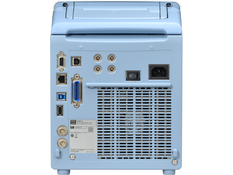
Gigabit Ethernet and USB 3.0 data transfers are standard, making it easier to work with large data sets. Optional internal 60 GB SSD stores more waveforms than ever. The faster internal communication rates enable higher memory and faster update rates so you never miss a signal. Switch seamlessly between tapping, pinching and dragging the touchscreen or using the precise, tactile hardware controls so you can personalize the interaction that’s best for you.
Measurements
Save time by performing on-board measurements.Twenty-nine common waveform parameter measurements are included. Automated measurement of up to 30 simultaneous measurements is available to provide more insight directly inside the instrument.

Dual Zoom
An independent zoom processor rapidly zooms into data even at the maximum of 500 Megapoints. Dual zoom makes it easy to see events separated in time, choose specific input channels to display, and even auto scroll forwards or backwards in time. Zoom Search finds edges, patterns, pulsewidths, or timeout conditions for easier location of interesting data.

FFT Spectral Analysis
Perform up to 2 simultaneous FFT functions, using the current waveform or a running average.

Triggering
A new completely digital triggering system enables lower timing jitter and improved vertical level accuracy for precise response. Trigger modes available include:
- Edge (Rise/Fall/Both)
- Edge OR
- Pattern
- Pulse Width
- Rise/Fall Time
- Runt
- Timeout
- Window (upper and lower limits)
- Window OR
- Interval
- Serial (supporting installed serial bus options)
- TV (NTSC/PAL/SDTV/HDTV/user-defined)
- A Delay B
- A to B(n)
History
Determining cause and effect relationships is a daily task for design and validation phases of mechatronics projects. To provide the necessary extensive data sets, Yokogawa oscilloscopes take advantage of the large internal storage to retain data from previous capture events. Because the actual waveform data is stored, these events are available for browsing, visualization, measurement and searching using the History feature. Up to 100,000 previous captures are available depending on the record size and sampling rate.

Displaying the History List shows all available captures with timestamps. Click on any entry to display the data on the screen for interaction.
Search box
When visualizing all captures in history memory, it’s easy to see an outlier waveform. Using the search box and the touchscreen, it’s easy to draw search conditions directly on the waveform and isolate the occurrence.

The search box (white box) is used to isolate signals falling within its boundaries, making it easier to deal with thousands of data sets simultaneously. Here, two glitches are highlighted for Search.

Now the List view shows only the two waveforms matching the Search results, allowing the user to locate them in time or perform further measurements.
Statistics
Single measurements are very informative, but many projects require statistical measurements across a large data set. The DLM3000 can also perform measurements across the entire history memory, providing statistical analysis of maximum, minimum, mean, and standard deviation. For inspection of unusual measurements, the List function displays all values, indicating maxima and minima with arrow symbols, and tapping or selecting any measurement opens that historical data set for further observation.

Executing History Statistics reveals the maximum, minimum, mean and standard deviation of all calculated measurements. Count displays the number of waveforms evaluated.
Switching Loss
The Power Analysis option enables automatic calculations for Safe Operating Area (SOA), I2t and Switching Loss. The switching loss feature automatically detects switching cycles and relevant regions of switch mode power supply (SMPS) signals to calculate several parameters.

Automotive and Embedded Serial Bus Features
Communication between electronics control units (ECU's), sensors and actuators is especially important to ensure proper vehicle performance. Rapidly troubleshoot and validate popular automotive serial buses with CAN, CAN FD, LIN, SENT, CXPI and PSI5 Airbag options. Simultaneously plot physical layer and decoded data, search for specific data values or use data items as a trigger condition. Yokogawa’s proprietary auto setup function analyzes the input signal and complicated trigger / decode settings such as bit rate and threshold level are done automatically. This feature not only saves time but also is a very powerful feature that allows you to start parsing quickly even when bit rates and other signal conditions are unknown.
List view displays the timestamp and the data of each packet within the capture, and clicking on any packet immediately zooms into that packet for inspection. This is especially important when combined with Yokogawa's long Time/Division capabilities, when numerous frames are visible on a single screen.
SPI, UART and I2C options are also available for general purpose and consumer device communication applications.

Up to four serial buses can be configured and inspected simultaneously, for systems integration and complex control schemes.

Get Answers Faster with a New CPU Platform

The totally new CPU platform of the DLM3000 is equipped with Gigabit Ethernet and USB 3.0 (file transfer) as standard communication interfaces, handling data faster than ever. For example, DLM3000 is 10 times faster at saving to internal storage and about 10 times faster when transferring to a PC (when SSD internal storage and USB 3.0 file transfer are used).
Get answers faster, even with large data sets.
For full model information and available options please download the brochure.
| Model Name | Bandwidth | Channels |
|---|---|---|
| DLM3054 | 500 MHz | 4 / 3 + 8-bit logic |
| DLM3052 | 500 MHz | 2 |
| DLM3034 | 350 MHz | 4 / 3 + 8-bit logic |
| DLM3032 | 350 MHz | 2 |
| DLM3024 | 200 MHz | 4 / 3 + 8-bit logic |
| DLM3022 | 200 MHz | 2 |
Four-channel models feature switchable fourth channel that converts into an 8-bit logic analyzer input with a push of a button.

【search key】 DLM3, DLM30, DLM300, DLM, DL

【search key】 DLM3, DLM30, DLM300, DLM, DL


This training module covers the following topics:
- Introduction & Installation
- Basics of Xviewer
- Advanced features
- Video Demonstrations
Brochures
Instruction Manuals
- DLM3022, DLM3032, DLM3052 Digital Oscilloscope/DLM3024, DLM3034, DLM3054 Mixed Signal Oscilloscope Features Guide (4.9 MB)
- DLM3022, DLM3032, DLM3052 Digital Oscilloscope/DLM3024, DLM3034, DLM3054 Mixed Signal Oscilloscope User's Manual (10.9 MB)
- DLM3022, DLM3032, DLM3052 Digital Oscilloscope/DLM3024, DLM3034, DLM3054 Mixed Signal Oscilloscope Getting Started Guide (7.3 MB)
- DLM3022, DLM3032, DLM3052 Digital Oscilloscope/DLM3024, DLM3034, DLM3054 Mixed Signal Oscilloscope Operation Guide (1.6 MB)
- DLM3022,DLM3032,DLM3052 Digital Oscilloscope/DLM3024,DLM3034,DLM3054 Mixed Signal Oscilloscope Communication Interface User's Manual (6.2 MB)
- Model 709811 Additional Option License for the DLM3000 User's Manual (229 KB)
Software
- IS8000 Integrated Software Platform
- Xviewer 701992 / XviewerLITE
- Xwirepuller
- WDF File Access Library
- MATLAB WDF Access Toolbox
- Symbol Editor
- Mask Pattern Editor
- DL-Term
- Yokogawa WDF DataPlugin ( NATIONAL INSTRUMENTS Web Page )
- USB Drivers
- TMCTL
- LabVIEW Drivers for DLM3000 ( NATIONAL INSTRUMENTS Web Page )
Firmware
Drawings
Product Overviews


The Yokogawa DLM3000 Mixed Signal Oscilloscopes, oscilloscope features a brand-new computing platform and available power supply analysis functions.

The DLM3000 Mixed Signal Oscilloscopes Automotive Serial Bus features can display up to four simultaneous serial buses and decoded data.
Yokogawa has launched a new range of high frequency, high voltage differential oscilloscope probes, combining proven features of its existing probes with new capabilities.
The new Model 701949 and 702907 passive oscilloscope probes from Yokogawa are intended to expand the usability and applications of Yokogawa’s DLM3000 Mixed Signal Oscilloscope.
Time limited offer:
Buy the new DLM3000 Mixed Signal Oscilloscope and get 50% off on any Vehicle Serial Bus Analysis option.

