DLM5000 Series Mixed Signal Oscilloscope


Best Mixed Signal Oscilloscope
As the creator of the world’s first 8 channel oscilloscope, and with over 100 years of industry experience, the DLM5000 is Yokogawa’s latest addition to our line-up and takes you beyond 8 channels. Adaptability is a key requirement during the development of high-performance and intelligent power-semiconductor technologies and mechatronics applied in a modern electric vehicles, motor controls, and energy efficient electronic designs. Combining a large, highly responsive touchscreen and a traditional oscilloscope panel, the 4-to-8 channel DLM5000 mixed signal oscilloscope allows users to easily navigate through a wealth of analysis features at the touch of their fingertips.
What is a mixed signal oscilloscope?
The best mixed signal oscilloscopes effectively gather and graph electrical signal data for logic analysis through multiple channels.
What is vp on a mixed signal oscilloscope?
VP, or peak voltage, on the DLM5000 mixed signal oscilloscope is ±1400 Vpeak.
Adaptable for your Unique Testing Requirements
- 8 analog channels, 32 bits of logic
- Additional math channels
- Vehicle serial bus
- DLMsync supports multi-unit synchronization extending measurements up to 16 channels
Trusted, Dependable Measurements
- Low residual noise
- Extensive voltage ranges
- A variety of real-time low pass filters
- View 100,000 previously captured waveforms using the unique history memory
- Purpose-built operating system

Simplicity at your Fingertips
- Highly responsive touchscreen
- Traditional oscilloscope control panel
- Light, compact 8-channel scope


Basic functions ideal for circuit evaluation/software debugging
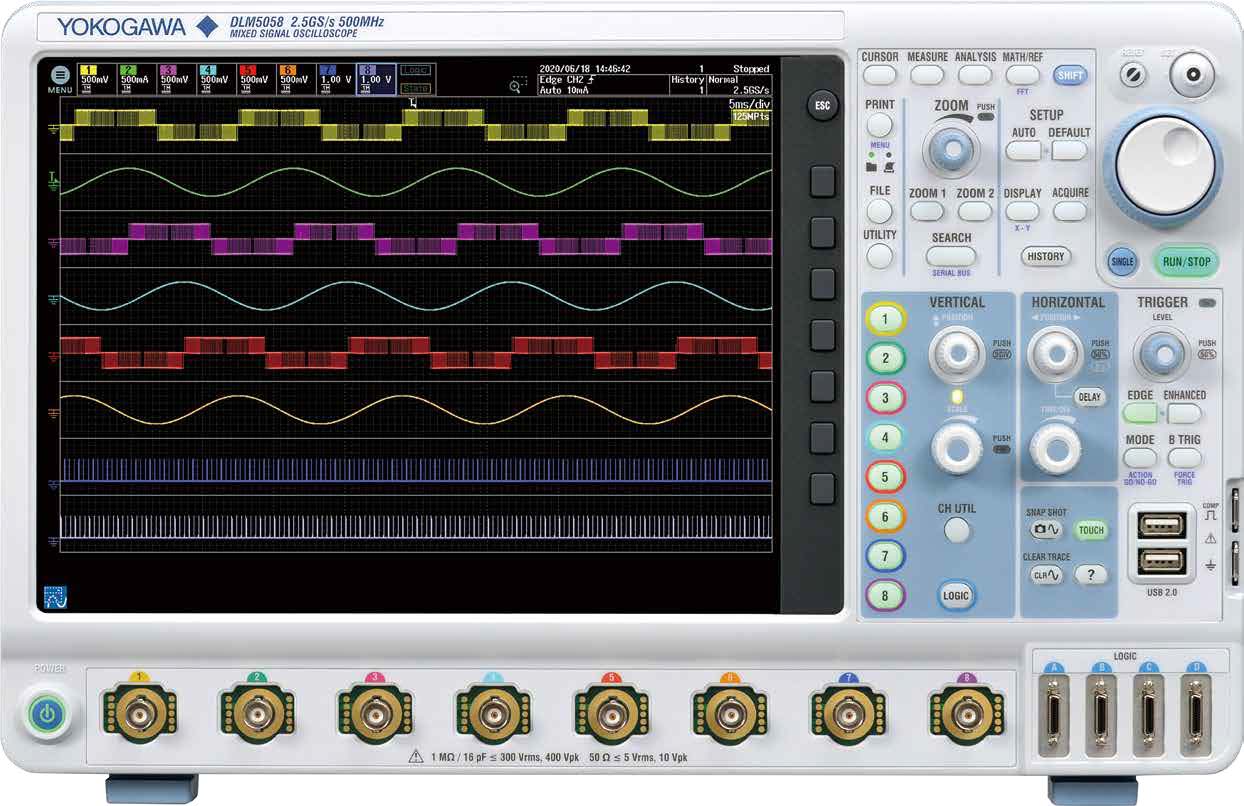
8 Analog ch + 32 bits of logic are collectively measured by one unit.
A single DLM5000 has 8 analog channels and 32 bits of logic, which usually requires two mixed signal oscilloscopes. By viewing sensor signals and amplifier inputs and outputs on the analog channels and serial/parallel bus signals on the logic channel, one unit is sufficient for embedded system debugging. The 4 ch model has been newly added to the series lineup.

12.1 inch large screen provides a comfortable debugging environment
Equipped with a 12.1-inch large touch screen. The large screen is useful for observing analog signals in detail and displaying information for debugging, such as parameters, zoom screen, XY display, and FFT analysis results.
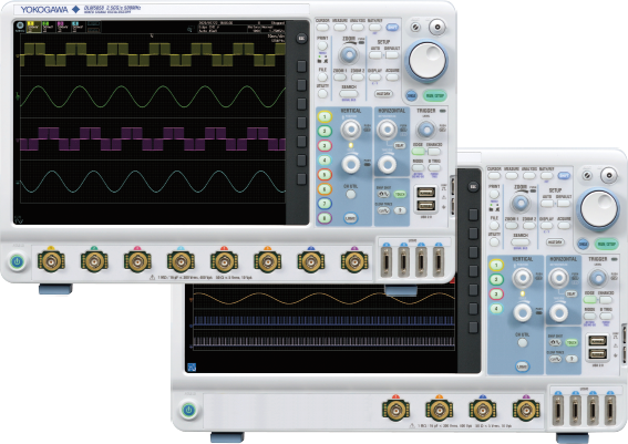
Easy to carry and measures quickly
While the DLM5000 is a large screen model with multichannel inputs, it comes in a portable, thin & lightweight design. The instrument starts up from OFF to waveform display in 18 seconds. You can start measurement work immediately.

Up to 2.5 GS/s (8 channels at the same time), Up to 500 Mpoints long memory
The evaluation of an embedded system requires the verification of its operation over a relatively long period of time with software commands and the simultaneous viewing of waveforms of high-speed signals such as clock noise. The DLM5000 is equipped with a memory that allows waveform capture of 50 Mpoints in single mode/12.5 Mpoints in repeat mode. You can observe waveforms with very few omissions. If 500 Mpoints memory (optional) is installed, 0.2 seconds waveform can be captured even at 2.5 GS/s sample rate.


Two-unit connection function "DLMsync" in response to the request for more channels (/SYN option)
Connecting two DLM5000s (with /SYN option) with a dedicated cable (701982) enables synchronous measurement of up to 16 analog channels. Captured waveforms are displayed on each unit. Triggers operate in common, and common items, such as memory length, sampling rate, acquisition settings and horizontal axis scale settings, are linked, so they can be used like a single 16-channel oscilloscope. You can connect 4 ch models too, so “8 + 4 = 12 channels” or “4 + 4 = 8 channels” is also possible.

You can replay waveforms later on, so you'll never miss an abnormal waveform
Original history function
Automatically save previously captured waveforms With the DLM5000 series, up to 100000 previously captured waveforms can be saved in the acquisition memory. With the History function, you can display just one or all of the previously captured waveforms (history waveforms) on screen. You can also perform cursor measurement, computation, and other operations on history waveforms. Using the History function, you can analyze rarely-occurring abnormal signals even when an appropriate trigger condition is hard to find because its waveform shapes are not constant.

History search function
Various and powerful search methods are available to search up to 100000 waveforms for events meeting your custom requirements. Intuitive and simple waveform search functions are provided. For example, you can specify a rectangular zone that captures a part of a waveform on the screen, a zone that covers an entire measured waveform, or a polygonal zone. If you know a value of interest, such as an abnormal value of voltage or pulse width, you can search history waveforms using waveform parameters.

Zoom & search function
Multi-channel waveforms captured in the long memory need to be zoomed in vertically and horizontally for detailed viewing. The DLM5000 has the dedicated zoom keys and knob, allowing you to quickly zoom in on the part you want to see. You can also specify the area you want to zoom in on by using the the touch screen.
Zoom two locations simultaneously
You can display two zoomed waveforms with different time axis scales at the same time. Also, use Auto Scroll to sweep the zoom window across the waveforms automatically. Being able to zoom in on two distant locations at the same time, such as “cause” and “effect” of a certain event, or to display them with different zoom factors is very useful for software debugging.
Zoom search function
Use several search criteria to automatically find and zoom into features in the waveform for further inspection. The locations of the found waveforms are marked on screen.
Waveform search criteria
Edge, edge (qualified), state/pattern, pulse width, state width, serial bus (only on models with the serial bus analysis option).

Touchscreen
By using the touchscreen to move the waveform position, change the scale, move the cursor, and such, you can operate the instrument without taking your eyes off the waveform. If you want to zoom in a part of the waveform, use Rect Zoom for easy zooming by swiping your finger diagonally across the screen to specify the area. To select items on the dialog box, you can directly touch them, which eliminates the trouble of using select keys.

Large selection of triggers
— Trigger function captures combined analog/digital complex waveforms —
The DLM5000 series comes with a variety of easy-to-configure triggers combining analog and logic inputs such as edge, enhanced, and B triggers. By using a digital trigger system, trigger errors are minimized.

Filter functions
Real time filter with optimum noise reduction supports a wide range of frequencies — from 8 kHz to 200 MHz —
Each channel has 14 low pass filters available with cutoff frequencies from 8 kHz to 200 MHz. Waveforms are filtered prior to storage in memory. Real-time filters allow for stable triggering of superimposed noise signals.

Logic signal measurement and analysis
The flexible MSO inputs are included as standard. This enables the DLM5000 to be converted to a 8 analog and 16 digital input MSO. With the /L32 option, up to 32 logic signals can be measured. Bus/State display and optional DA calculation function, which is useful for evaluating AD/ DA converters, are also provided.

Features designed for productivity
Measure function and statistics
Twenty-nine waveform parameter measurements are included. Automated measurement of up to 30 simultaneous measurements is available. Statistical values can also be measured continuously, cycle-by-cycle or using history memory. In addition, cycle-by-cycle parameter measurement is possible to calculate fluctuations of a captured waveform.
FFT analysis
Up to 4 FFT analyses can be performed simultaneously. FFT can be performed on computed waveforms in addition to the actual waveforms on CH1 to CH8. The peak detection function that automatically detects the spurious frequency is a useful feature for searching for a noise source, such as clock and power supply switching noise.

Statistical calculation of waveform parameters
For repetitive waveforms, a large number of periodic waveforms are captured on the memory. The DLM5000 can statistically analyze the parameters of repetitive waveforms. Jitter measurement and level fluctuation analysis are possible.

Snapshot
By pressing the “camera” key to the lower right of the screen, you can freeze a white trace of the currently displayed waveform on the screen. You can press the key repeatedly and conveniently leave traces for comparing multiple waveforms.
Thumbnails of saved files
Display thumbnails of saved waveforms, waveform images, and Wave Zone files for easier browsing, copying or deleting. A full-size view shows even more details.

Action on trigger, GO/NO-GO
GO/NO-GO automates pass or fail determination for trigger conditions, waveforms, measured parameters, and other criteria. Actions automate buzzer sounds, file saving, or email notification. Waveforms in which an abnormality occurred can be saved for confirmation and analysis of the phenomena at a later time.

IEEE1588 time synchronization function
High-precision synchronous measurement is possible with a DL950 and WT5000 that are time-synchronized with IEEE1588 signals.
In addition, these measurement data sets can be displayed and analyzed at the same time on the IS8000.
Application-specific analysis options
User defined math option (/G02)
Equations can be arbitrarily created using a suite of operators such as trigonometric and logarithmic operators, integration and differentiation, pulse width operators, phase measurement and digital to analog conversion.
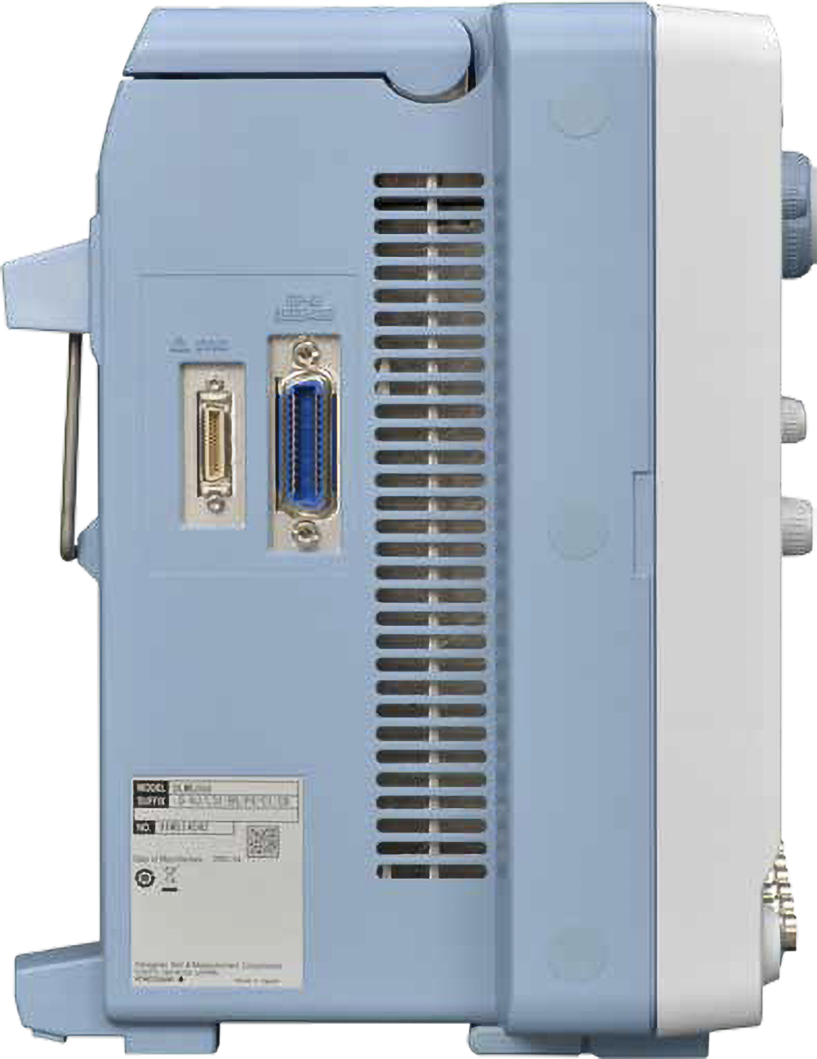
Wide range of interfaces and software
Increase work efficiently by using PC Gigabit Ethernet and USB 3.01 as standard communication interfaces DLM5000’s long memory is useful for suppressing failure in capturing waveforms, such as the history function, but it takes time to transfer data to a PC. With the standard-equipped Gigabit Ethernet and USB 3.0, the DLM5000 is approximately 10 times faster at saving data to the internal storage and at transferring data to a PC.2 Get answers faster, even with large data sets.
1USB function only. USB host function uses USB 2.0 communication.
2 When /C8 option (SSD) is installed for internal storage and USB 3.0 mass storage connection is used for transfer. Compare with the conventional model (DLM4000).


Multi-channel measurement application
Motor control & inverter circuit development
Limitation of 4 ch scope
Whole-system measurement is impossible with a four channel scope; the real difficulty is measuring the timing between IGBT gate signals within the inverter. Voltage and current measurements between 3 phases and the IO of the motor driver IC is a very challenging test with a four channel scope. The truly practical solution is an eight channel MSO.
Electronic control unite & mechatronic test
Limitation of 4 ch MSO
The additional logic inputs of a four-channel MSO mixed signal oscilloscope provides enough channels, but this method has a blind-spot. Digital waveform analysis using logic inputs alone cannot reveal anomalies such as voltage drift, noise, distortion or ringing, and measure rise-fall times. ECU testing requires stringent examination of all digital waveforms – and analog input channels are the best tool for the job.
8 ch
The key to efficient and reliable high performance electric motors is the modern inverter design, or ‘Intelligent Power Module’. Multi-channel, highspeed waveform measurement is an absolute necessity. Four channels are simply not enough. Boasting eight true analog inputs, the DLM5000 empowers today’s engineer with a convenient and comprehensive measurement system.
Numerous I/O analog, digital, and serial-bus waveforms surrounding the Electronic Control Unit (ECU) must be measured. The DLM5000 offers ample channel-count and architecture to monitor eight analog channels and up to 24-bits of logic input while simultaneously performing protocol analysis such as UART, I2C, SPI, CAN, CAN FD, LIN, CXPI and FlexRay. The DLM5000 can speed up the R&D process when four channels are not enough.


|
Model |
Description |
|---|---|
|
DLM5038 |
Mixed Signal Oscilloscope: 8 ch, 350 MHZ |
|
DLM5058 |
Mixed Signal Oscilloscope: 8 ch, 500 MHZ |
|
DLM5034 |
Mixed Signal Oscilloscope: 4 ch, 350 MHZ |
|
DLM5054 |
Mixed Signal Oscilloscope: 4 ch, 500 MHZ |
Power supply analysis option (/G03)
Switching loss analysis
Calculate switching loss [V(t) × i(t)] over long test cycles utilizing the long built-in memory. A wide variety of switching loss analyses are supported, including turn-on/off loss calculation, loss including continuity loss, and loss over long cycles of 50 Hz/60 Hz power line.

Power parameter measurement
Measure power parameters automatically for up to four pairs of voltage and current waveforms, such as active power, apparent power, power factor, and more. Cycle statistics and history statistics can also be calculated.

Serial analysis function options (/F01 to /F06)
UART (RS232) /I2C/SPI/CAN/CAN FD/LIN/FlexRay/SENT/CXPI/PSI5 Airbag
Dedicated trigger and analysis options are available for various serial buses of both in-vehicle and embedded systems. Logic input can also be used for I2C/SPI/UART/SENT. When it is not necessary to observe waveform quality of a bus, decoding or analysis using logic inputs is possible.
Unique auto setup
Yokogawa’s proprietary auto setup function automatically analyzes the input signal and complex parameters such as bit rate and threshold level, selecting the optimal settings in seconds. This feature not only saves time but is also a powerful debugging feature when the bit rate and other parameters are unknown.
Simultaneous analysis of up to 4 buses
Perform high-speed simultaneous analysis on up to four different serial buses operating at different speeds. Extensive search capabilities enhance the usability, allowing the user to find specific data in the very long memory. The dual-zoom facility means that different buses can be viewed and debugged alongside each other.


- Construction and verification of SENT communication system
- Accurate, reliable data transmission at low cost


While accurate rise time measurements have become easier to make, it remains, nonetheless, quite easy to overlook error contributions due to not only the oscilloscope but also the probe. And, while the error contributed by a scope's finite step-response (rise time) is often accounted for, that contributed by the probe is often overlooked.

DLM5000_Simultaneous_analysis_of_eight_CAN_buses

Frequency to Voltage Conversion Problem: A transducer produces a sine-wave output dependant on the voltage-input; here is how to decode that output with a scope or a ScopeCorder. For 3kV input, the transducer ...
The free software DL-GATE can be used for the following products only:DL1700E seriesDL7400 series (firmware version after 1.32)DL1600 series (firmware version after 1.13)DL750 series (firmware version after ...

This training module covers the following topics:
- Introduction & Installation
- Basics of Xviewer
- Advanced features
- Video Demonstrations
Brochures
- DLM5000HD Series High Definition Oscilloscope/ DLM5000 Series Mixed signal Oscilloscope (7.4 MB)
- Probes and accessories for Oscilloscopes (2.3 MB)
- Features & Benefits Flyer DLM5000 (146 KB)
Instruction Manuals
- DLM5034, DLM5038, DLM5054, DLM5058 Mixed Signal Oscilloscope Features Guide (5.0 MB)
- DLM5034, DLM5038, DLM5054, DLM5058 Mixed Signal Oscilloscope USER'S MANUAL (14.0 MB)
- DLM5034, DLM5038, DLM5054, DLM5058 Mixed Signal Oscilloscope Getting Started Guide (7.2 MB)
- DLM5034, DLM5038, DLM5054, DLM5058 Mixed Signal Oscilloscope Operation Guide (1.3 MB)
- DLM5034, DLM5038, DLM5054, DLM5058 Mixed Signal Oscilloscope Communication Interface USER'S MANUAL (6.5 MB)
- Model 709821 Additional Option License for the DLM5000 User's Manual (244 KB)
Software
- IS8000 Integrated Software Platform
- Xviewer 701992 / XviewerLITE
- Xwirepuller
- DL-Term
- MATLAB WDF Access Toolbox
- Symbol Editor
- Mask Pattern Editor
- WDF File Access Library
- USB Drivers
- TMCTL
- LabVIEW drivers for DLM5000 ( NATIONAL INSTRUMENTS Web Page )
Firmware
Drawings
Product Overviews
- Yokogawa DLM5000 mixed-signal oscilloscope
- 4-to-8 channels
- Easily navigate through a wealth of analysis features


Test and measurement engineering work groups can have differing priorities and requirements, which often results in multiple instrumentation systems and data file formats, as well as incompatible reporting. This lack of effective communication between groups and instruments causes decreased efficiency and quality and increased spending and time to market. Unify test and measurement instrumentation, software, and data across engineering teams with a suite of solutions that caters to the different needs of engineering work groups, including accurate power data, fast sampling rates, long recordings of multiple different input types, and insights into waveform data.
Yokogawa has launched a new range of high frequency, high voltage differential oscilloscope probes, combining proven features of its existing probes with new capabilities.
Yokogawa has launched the DLM5000, a new generation mixed signal oscilloscope with options for four or eight analog inputs.

