DLM2000 Mixed Signal Oscilloscopes (DISCONTINUED)

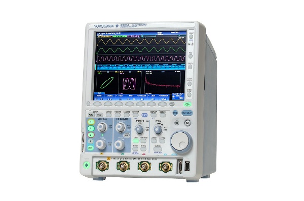

The DLM2000 is a bench-top oscilloscope for electronic design or debug. It's ergonomic and easy to use, and packed with features. With bandwidths from 200 to 500 MHz and memory from up to 250 Mpoints, you can be certain there is a DLM2000 to meet your application and budget. With the DLM2000's industry first “flexible MSO input”, you can choose to activate channel four as an analog input, or use it to acquire 8 bits of logic instead. Modern electronics include analog and digital circuitry—and the DLM2000’s flexible MSO input lets you measure both, including mixed signal triggers and decoding of parallel or serial bit patterns. Options available include functionality for CAN, CAN FD, LIN, SENT, UART, I2C, SPI, PSI5 and CXPI bus analysis, and power supply analysis.
Compact & intuitive operation
Easy-to-Use & Easy-to-See
Easy to use. Portrait body + large screen makes display easy to see.
We elevated the large (8.4-inch) LCD screen up into the line of sight. Also, the portrait format saves space on the desk or test bench. A compact "personal oscilloscope" designed for easy viewing and ease of use.


Signal Observation on 4 channels or more...
Switch between analog and logic channels
Flexible MSO input
Four channels is not sufficient to view the functioning of digital control circuits. The DLM2000 series converts 4 ch of analog input to 8-bit logic, and functions as a 3 ch analog + 8-bit logic MSO (mixed signal oscilloscope).
|
|
||
| 4 ch analog | 3 ch analog + 8-bit logic | |

The performance of up to 11 inputs by converting to logic
Using logic input, up to 11 input signals can be observed simultaneously as 3 ch of analog and 8-bit logic. It is not only possible to use logic input for observation of data and control signals, or as a trigger source, but also for logic
input analysis of I2C and SPI serial busses.

Fast data processing with ScopeCORE
With our proprietary ScopeCORE fast data processing IC, real time display is possible even signals of 11 inputs.

DLM2000 Series Lineup
| Item | Model | DLM2022 710105 |
DLM2032 710115 |
DLM2052 710125 |
DLM2024 710110 |
DLM2034 710120 |
DLM2054 710130 |
| Analog Input channels | 2 | 4* | |||||
| Logic input | - | 8bit | |||||
| Maximum sampling rate | 2.5 GS/s (interleave ON) | ||||||
| Frequency Characteristics | 200 MHz | 350 MHz | 500 MHz | 200 MHz | 350 MHz | 500 MHz | |
| Maximum Record Length | 62.5 Mpoints (Single measurement, interleave ON) | 250 Mpoints (Single measurement, memory length: /M3, interleave ON) | |||||
Largest long memory within the class
| Continuous Measurement | Single-Shot Measurement | ||
| 2 ch, 4 ch same | With 4 ch (With 2ch for DLM20x2) | With 2 ch (With 1ch for DLM20x2) | |
| /M1, /M1S memory option (standard) | 6.25 Mpoints | 25 Mpoints | 62.5 Mpoints |
| /M2 memory option | 12.5 Mpoints | 62.5 Mpoints | 125 Mpoints |
| /M3 memory option | 25 Mpoints | 125 Mpoints | 250 Mpoints |
Note:The /M1, /M2, /M3 memory expansion options are only available on 4ch models. The /M1S option is only available on 2ch models.
Large capacity memory up to 250 Mpoints
Long memory is necessary to keep high speed sample rate in long term measurement.
Measuring time = Memory length/Sample rate
If 250 Mpoints (Memory expansion option /M3) is installed, Max. 0.2 sec waveform can be captured even at 1.25 GS/s sample rate when taking 2 ch measurements in Single mode.


History function - Automatically save previously captured waveform
With the DLM2000 series, up to 50000 previously captured waveforms can be saved in the acquisition memory. With the History function, you can display just one or all of the previously captured waveforms (history waveforms) on screen. You can also perform cursor measurement, computation, and other operations on history waveforms. Using the History function, you can analyze rarely-occurring abnormal signals.

Trigger function capturing combined analog/digital waveforms
The DLM2000 series comes with a variety of easy-to-configure triggers combining analog and logic inputs such as edge, enhanced, and B triggers.

Trigger Function Example
A to B(n) Trigger:
Trigger on the 7th edge of signal on B. This is effective for measurements with shifted timing, such as non-standard video signal vertical/horizontal periods or motor reference position pulses and drive pulses.

Serial Pattern Trigger (user defined):
Trigger on an arbitrarily set pattern of up to 128 bits. This is effective for detecting ID/Data and other portions of proprietary communication formats.

Dual Bus Trigger:
Trigger on a combination of CAN and LIN bus triggers. I2C + SPI bus triggers, and other combinations are possible.
Trigger when either LIN or CAN bus signal conditions become true.

Capture & Display Zoom and Search Functions
Real time Filter with optimum noise reduction supports a wide range of frequencies (from 8 kHz to 200 MHz)
The DLM2000 series has two types of filters, one processed at the input circuit and one based on MATH functions. These filters are effective for rejecting unwanted signals, allowing observation of only the desired bandwidths.
Real Time Filters
Each channel has 14 low pass filters available from 8 kHz to 200 MHz. The filtered data is stored in internal memory.
Cutoff Frequencies:
200 MHz, 100 MHz, 20 MHz, 10 MHz, 5 MHz,
2 MHz, 1 MHz, 500 kHz, 250 kHz, 125 kHz,
62.5 kHz, 32 kHz, 16 kHz, and 8 kHz

Two fully independent zoom windows
Zoom two locations simultaneously
Combined with the advanced search and cursor/parameter measurement capabilities, the two zoom windows enable users, for example, to see the waveform detail of two parts of the acquisition which can be separated by a long time period.

Large capacity memory gives you a variety of waveform search functions
Two types of waveform searching:
Normally, searching for data takes time and costs money, and long memory is useless without functions for extracting desired data from a large capacity memory. That's why the DLM2000 series does not simply offer long memory, it also provides powerful waveform search functions.
Searching for data in a single screen: the Zoom Search function
Quickly find and markabnormal signals in long and multiple waveform acquisitions.
( shows the current location).

Waveform Search Criteria
Single waveform acquisitions of up to 250 MPoints can be searched using various criteria such as edges, state patterns, pulse widths and serial bus patterns (optional).
Searching for history waveforms: the History Search Function
The history memory can be searched to find matching criteria in up to 50,000 acquisitions.


Searching for waveforms in zones created by moving measured waveforms up/down/left/right.

Search for waveforms that pass through/do not pass through a rectangular zone placed on screen.
Useful Functions - Fastest and most capable analysis
Measure function and statistics
30 waveform parameters from a total of 29 different types can be displayed simultaneously with a high update rate. These include: maximum, minimum, peak-to-peak, pulse width, period, frequency, rise and fall times, and the delay between channels.
The statistics of repetitively measured parameters can also be displayed, such as the mean, maximum, minimum and standard deviation.

Trend and histogram displays
To observe the fluctuations of measured parameters, it is possible to display them as trends. Period-to-period changes can then be easily seen. The variation of parameters can also be displayed as histograms thus providing a statistical visualization.

Measure voltage and time differences automatically
Line or waveform marker cursors can be placed on different displayed waveforms and the absolute values of voltage and time, and their differences, can be simply displayed. A degree cursor can also be used by
converting the time axis into a position/degree axis. Six types of cursor are available.

FFT Frequency Domain Analysis
2 FFT analyses can be performed simultaneously. The source data can be either from input channels or from the results of mathematical computations. In addition to the standard Power Spectrum calculations, a suite of FFT functions are available with the /G2 user defined math option installed.

Keeps waveforms with one push
By pressing the SNAPSHOT key to the lower right of the screen, you can freeze a white trace of the currently displayed waveform on the screen. You can press the key repeatedly and conveniently leave traces for comparing multiple waveforms. Also, snapshot data recorded on screen can be saved or loaded as files, and can be recalled for use as reference waveforms when making comparisons.

Displays stored files in thumbnail format
Thumbnails of waveform data, waveform image data, and Wave-Zone files can be displayed. The image and file names are shown so that you can view screen image contents while copying or deleting files. A file can be enlarged to confirm the data.

Has a GO/NO-GO function
The GO/NO-GOfunction can be used to test the results of parameter measurements, trigger conditions and other criteria and automatically save or print data, send an e-mail or activate external equipment such as a buzzer.

Graphical online help
You can view detailed graphical explanations of the oscilloscope's functions by pressing the "?" key in the lower left of the screen. This lets you get help on functions and operations on screen without having to consult the user's manual.

Additional Option License for DLM2000
This is a license product for adding applicable optional features on to DLM2000 series on your own.
It is necessary to update main unit firmware in advance to V3.00 and above* in order to apply this license.
This license is only valid for 4 ch models.
* Firmware version 3.70 or higher is required to apply -F9, -X1 licenses.
* Firmware version 4.70 or higher is required to apply -10, -11 licenses.
* Firmware version 5.01 or higher is required to apply -F4, -F6, -F7, -F8 licenses.
| Model | Suffix code | Description |
|---|---|---|
| 709810 | -G2 | User defined math (4 ch model only) |
| -G3 | Power supply analysis function (4 ch model only) | |
| -G4 | Power supply analysis function (includes G2) (4 ch model only) | |
| -F1 | UART trigger and analysis (4 ch model only) | |
| -F2 | I²C + SPI trigger and analysis (4 ch model only) | |
| -F3 | UART + I²C + SPI trigger and analysis (4 ch model only) | |
| -F4 | CAN + LIN trigger and analysis + CXPI analysis (4 ch model only) | |
| -F5 | FlexRay trigger and analysis (4 ch model only) | |
| -F6 | FlexRay + CAN + LIN trigger and analysis + CXPI analysis (4 ch model only) | |
| -F7 | CAN+CAN FD+LIN trigger and analysis + CXPI analysis (4 ch model only) | |
| -F8 | FlexRay+CAN+CAN FD+LIN trigger and analysis + CXPI analysis (4 ch model only) | |
| -F9 | SENT analysis (4 ch model only) | |
| -10 | PSI5 analysis (4 ch model only) | |
| -11 | SENT+PSI5 analysis (4 ch model only) | |
| -X1 | F4 -> F7 or F6 -> F8 (adds CAN FD) |
Serial analysis function options (/F1 to /F11)
- UART (RS232)/I²C/SPI/CAN/CAN FD/LIN/FlexRay/SENT / PSI5 / CXPI -
Dedicated trigger and analysis options are available for FlexRay, CAN, CAN FD, LIN, SENT, UART, I2C, SPI, PSI5 and CXPI* serial buses.
Intelligent serial bus auto setup: For most buses a wide variety of trigger combinations can be set, including ID and Data combinations, which can also be combined with conventional edge triggers. A serial bus
auto-setup enables the MSO to be quickly configured. The user therefore does not need detailed knowledge of the bus frame format in order to trend and record serial data.
Simultaneous analyses of four different busses: Up to four busses can be analyzed simultaneously. Waveforms and analysis results from busses with different speeds can be displayed using 2 Zoom windows.
Inputs supported for serial bus analysis
| I²C | SPI | UART | LIN | CAN | CAN FD | FlexRay | SENT | PSI5 | CXPI | |
|---|---|---|---|---|---|---|---|---|---|---|
| Analog Input | Yes | Yes | Yes | Yes | Yes | Yes | Yes | Yes | Yes | Yes |
| Logic Input | Yes | Yes | Yes | NA | NA | NA | NA | Yes | NA | NA |

Simultaneous analyses of I2C and SPI

Four bus decode and list display
Power Supply Analysis Option (/G3, /G4)
The /G3 and /G4 options enable switching loss, joule integral (i2t), SOA (safe operating area), harmonics based on EN61000-3-2, and other power parameters to be measured and analyzed.
Switching Loss Analysis
Using the long memory, the switching loss of the voltage and current input waveforms can be computed (V(t) X i(t)) over long time periods. The turn-on/off loss, the loss including the continuity loss, and the loss over many cycles of the 50 Hz/60 Hz power line can be calculated and analyzed.

Power parameter measurement
The MSO can also be used as a power meter by providing automated measurement of power parameters for up to two pairs of voltage and current waveforms, such as the active power, apparent power and power factor. These values can then be statistically processed and calculated.

Complement complex measurement tasks using a comprehensive suite of software tools.


- Released new firmware version 5.02.
- Released new firmware version 5.01.
- Added CXPI analysis option. (/F4,/F6,/F7,/F8)
- Released new firmware version 4.73.
- Increased the maximum number of trend display from 1 to 4 in the SENT analysis function. (/F9,/F10)
- New features added.
- /F10, /F11 (PSI5 analysis option)
- Released new firmware version 4.43.
- /F7, /F8 CAN FD analysis option revised to comply with ISO standard.
| Model | Description |
|---|---|
| 710105 | Digital Oscilloscope DLM2022: 2ch, 200MHz |
| 710110*1 | Mixed Signal Oscilloscope DLM2024 4ch, 200MHz |
| 710115 | Digital Oscilloscope DLM2032 2ch, 350MHz |
| 710120*1 | Mixed Signal Oscilloscope DLM2034 4ch, 350MHz |
| 710125 | Digital Oscilloscope DLM2052 2ch, 500MHz |
| 710130*1 | Mixed Signal Oscilloscope DLM2054 4ch, 500MHz |

700924 Differential Probe 1400V / 100 MHz
- Differential oscilloscope probe
- 100 MHz
- ±1400 V (DC + ACpeak) at 1000:1
- Power: Internal battery or probe power supply
- Works with Oscilloscopes, ScopeCorders


701920 Differential Probe 12V / 500 MHz
500 MHz, 10:1, Max. Differential Voltage: ±12 V (DC + ACpeak), Probe Power: probe power supply Work with 50 Ω input system oscilloscope

701921 Differential Probe 700V / 100 MHz
100 MHz, 100:1/10:1, Max. Differential Voltage: ±700 V (DC + ACpeak) at 100:1 attenuation, Probe Power: Internal battery or probe power supply

701922 Differential Probe 20V / 200 MHz
200 MHz, 10:1, Max. Differential Voltage: ±20 V (DC + ACpeak), Probe Power: probe power supply Work with 50 Ω input system oscilloscope

701926 Differential Probe 7000V / 50 MHz
50 MHz, 1000:1/100:1, Max. Differential Voltage: 5000 Vrms/7000 Vpeak (1000:1), Probe Power: Internal battery or probe power supply B9852MJ power cable is bundled Work with Oscilloscopes, ScopeCorders

High Voltage Differential Probe 701927
- 150 MHz bandwidth
- ±1.4 kV max. differential voltage
- 50 dB CMRR (1 MHz)
- Interface: Yokogawa DLM Series


30 A High BW Current Probe 701929
- 30 Arms maximum
- DC to 50 MHz bandwidth
- Interface: Yokogawa DLM Series


701936 Deskew correction signal source
- 701936 Deskew Correction Signal Source
- Improve switching-loss measurements by deskewing
- Accommodates both clamp-on current probes and through-type ‘CT' Current Transformers

High Voltage Passive Probe 701944
- 1000 Vrms, 400 MHz
- Impedance (50 MΩ | 7.5 pF)
- CAT II rating, 1.2 m
- 0 to +50 °C operating temp.

High Voltage Passive Probe 701945
- 1000 Vrms, 250 MHz
- Impedance (50 MΩ | 7.5 pF)
- CAT II rating, 3 m
- 0 to +50 °C operating temp.

701988 Logic Probe 100 MHz / 8-bit
- 8-bit, 1 MΩ input resistance (PBL100)
- Toggle frequency of 100 MHz

701989 Logic Probe 250 MHz / 8-bit
- 8-bit,100 kΩ input resistance (PBL250)
- Toggle frequency of 250 MHz

High Voltage Passive Probe 702906
- 1000 V (DC+ACpeak), 200 MHz
- Impedance (10 MΩ | 16 pF)
- CAT II rating, 2.5 m
- -40 to +85 °C operating temp.


701919 Probe Stand
- 701919 oscilloscope probe stand
- Flexible arm, heavy base to hold and stabilize 8-13mm probes
- Can simplify circuit board testing


701964 Soft carrying case for DLM2000
Three pockets are provided for storing accessories and the user’s manual.

366924 BNC to BNC 1m Cable
- 366924 BNC to BNC cable for oscilloscope
- 1m BNC wire
- Simultaneous measurement with 2 units
- Input external trigger signal

366925 BNC to BNC 2m Cable
BNC-BNC 2m. For connection to simultaneously measurement with 2 units, or for input external trigger signal.

- Construction and verification of SENT communication system
- Accurate, reliable data transmission at low cost

While accurate rise time measurements have become easier to make, it remains, nonetheless, quite easy to overlook error contributions due to not only the oscilloscope but also the probe. And, while the error contributed by a scope's finite step-response (rise time) is often accounted for, that contributed by the probe is often overlooked.

Mixed Signal Oscilloscopes DLM2000 Series
Serial Bus Analysis Application Note

The HDMI (High-Definition Multimedia Interface) standard is based on the DVI (Digital Visual Interface) standard. The HDMI standard has addressed the requirements for a next generation visual interface adapted by non PC applications such as DVD players or STB.
The AC Power Input in all Yokogawa instruments is designed as a 3-pin connection (one of which is a GND pin). In some parts of the world, PCs are sold with AC power cables that are 2-pin. Often times this means the ...
You can disable the soft menu from saving to a screenshot by setting the Mode to Normal through the Utility menu.
- Rated specification for channel to channel skew on the DLM2000 oscilloscope is 1 ns or less, where 1 ns typically denotes worst case scenario
- Verify same test conditions for both channels
The DL series instruments are capable of measuring the delay between traces or the delay between channels. The measured output value can be displayed in either time or degree. To setup the DL850 Scopecorder to measure delay, follow ...
The DLM2000 Series mixed signal oscilloscopes are capable of performing enhanced parameter measurements and calculations. This feature allows you to perform automated measurements of waveform parameters of two different areas. It ...
For the DLM2000 Mixed Signal Oscilloscope with user-defined math (G2 Option), you can calculate the ratio of two voltages in decibels. The formula for calculating the ratio of two voltages in dB is: dB = ...
Decimation is a technique used to reduce the total number of samples. You can use Xviewer to perform decimation on your waveform data files that have the WDF/WVF/ASCII CSV extension format. Decimation reduces the ...
With the DLM2000 series mixed signal oscilloscope, up to 20,000 previously captured waveforms can be saved into the acquisition memory. You can use the HISTORY function to search, display and save just one or all of ...
There are two methods to programmatically determine if the calculations for waveform parameters is completed on the DL series oscilloscopes. Send the :MEAS:WAIT? command. This will ensure that no other commands are ...
If your DL series oscilloscope is not measuring rise or fall time, it may be because you are attempting to measure asymmetric waveforms. It is not possible to perform automatic rise or fall time measurements on DL ...
High Resolution mode can be used to remove high frequency noise and increase vertical resolution. It achieves this by increasing the number of effective bits per data to 12-bits through digital and bandwidth filters.
- Unbalanced input, balanced input, isolated input, and differential input
- Types of inputs guide presentation
- Related products and solutions

The timestamp on the DLM2000 Mixed Signal Oscilloscope corresponds to the end of waveform acquisition and is the time of the very last acquisition. Likewise, the timestamp in history corresponds to the last waveform acquisition.Please ...
The DLM2000 Mixed Signal Oscilloscope have a unique feature that will allow you to save the timestamps in the History List. Please verify or update the firmware version on your DLM2000 to version 1.81 or later. There are two different save ...
Even though the display record length is shorter than the specified record length, measurement is made over the full record length. There is no function that allows you to move the display position to view the other ...
The Time Axis Accuracy is the accuracy of the A/D clock. It is not possible to directly measure the A/D clock and the A/D clock is not output from the ScopeCorder DL850/SL1400. To verify the accuracy of the A/D clock, you will ...
Please verify the following items: USB does not exceed 16 GB Latest firmware is installed on DLM2000 USB Format is FAT32 USB works properly on PC Test USB on another USB port If the problem persists, please ...
Yes, the DLM2000 Mixed Signal Oscilloscope can decode and analyze J1939.
Question:If the DL9000 Oscilloscopes is in normal trigger mode and no waveform acquisitions have been made i.e. the scope has not triggered, a query to the instrument using the :Waveform:Record or :History:Record? Minimum it returns ...
Can we upgrade the DLM2000 Mixed Signal Oscilloscope memory to /M2? No – DLM2000 Memory is factory only (must be ordered at time of new purchase); there is not a mod available for this type of upgrade.
Frequency to Voltage Conversion Problem: A transducer produces a sine-wave output dependant on the voltage-input; here is how to decode that output with a scope or a ScopeCorder. For 3kV input, the transducer ...
In the menu of GO/NO-GO Zone Editor determination, there is no menu option for setting the for measuring range.The measuring range can be set in the Area1 sub-menu of the Automated Waveform Measurement Parameter menu..
The DLM2000 Mixed Signal Oscilloscopes can save multiple waveform history data to 1 file when the file type is set to Binary format. However, when the file save type is set to ASCII, only the displayed waveform data can be saved regardless ...
When using voltage probes, please set the channel probe mode using the command :CHANnel:PROBe 10.00 or 0.01. When using current probe, please set the channel probe mode using the command :CHANnel:PROBe C10 or ...
The free software DL-GATE can be used for the following products only:DL1700E seriesDL7400 series (firmware version after 1.32)DL1600 series (firmware version after 1.13)DL750 series (firmware version after ...
The DLM2000 mixed signal oscilloscopes has a Serial Bus Analysis option from /F1 to /F4. This includes the CAN, LIN, UART, I2C, and SPI protocols. However, there is one more User-Defined Serial Bus Analysis, which is not an add-on ...
How to use SNTP on DL850 ScopeCorder The sequence below is very important for SNTP to work properly.1. Set DATE/TIME and GMT Time Difference to your location FIRST. EDT is -4 hours, EDT is -5 hours - as examples. 2. Set a SNTP ...
- The DLM2000 will prohibit any attempts to save a waveform in CSV format if the file is larger than 1.25 Mpts
- There are two methods to work around this issue
- Symbol editor for the DL9000/SB5000/DLM2000 instruments
- Two operating modes: CAN and LOGIC
- See Symbol Editor online software download page
The sanitation procedure for various Yokogawa oscilloscopes have been documented below. Please download the document or pdf that refers to your Yokogawa oscilloscope.
The Yokogawa .SNP file is a proprietary Yokogawa file format for saving waveform snapshots. This file has no relation to the Microsoft Snapshot Viewer program. The .SNP file can only be viewed on the oscilloscope.
Yes, the HDMI pinout carries the I2C on pins 15 and 16 of the HDMI connector cable. The HDCP (content protecting encryption keys) signal is carried on pins 15 and 16.
Please see the attached document for complete instructions on how to get connected to the DLM2000 Mixed Signal Oscilloscope using Xviewer.
Please download the attached document for detailed instructions on how to work around the DLM2000 Mixed Signal Oscilloscope ASCII record length limit Error Code 545
Please download the attached article. This article discusses the three types of display interpolation found in the Yokogawa DL9000 and SB5000 Digital Oscilloscopes. It is also applicable to other Yokogawa Oscilloscopes.
Yes, VXI-11 is required and needs to be enabled for the DLM2000 Mixed Signal Oscilloscope to connect properly to Xviewer when using an ethernet connection. If the VXI-11 option is unchecked, a connection failed message will appear. Related ...
Yes, DLM2000 Mixed Signal Oscilloscope has CE Certification. Please see attached documents for details.
Yes, the NAK CAN Bus Trigger is supported on the DLM2000 Mixed Signal Oscilloscope and DL9000 Digital Oscilloscope. DL9000: Refer to the IM 701310-51E (page 3-13)DLM2000: Refer to the IM 710105-02E (page 2-16)
The DLM2000 Mixed Signal Oscilloscope base model with standard storage memory capacity is 100MB. With the /C8 Option, the internal storage memory capacity is 1.8GB.
Although the DLM2000/DL9000 Mixed Signal Oscilloscope does not have a BoxAvg acquisition mode, there is an alternative method for achieving the same effect. The combination of Hi-Res mode and a low pass bandwidth filter will work in the same ...
The actual input limit for the DLM2000 Mixed Signal Oscilloscope is 212V (DC+ACpeak) for not only a 0.01 or 0.001 Hz AC signal but also a DC signal. The reason why 150 Vrms is indicated on the DLM2000 specification sheet is that the safety ...
There are three kinds of standards for which a differential probe is necessary: FlexRay CAN UART (Some but not all UART) It is not necessary to use a differential probe for the LIN, I2C and SPI standards.
- "Beat Method" for Inspecting an Oscilloscope’s Time Base Accuracy
- Inspect and verify time base accuracy
- Aliasing effect to create a "beat waveform."
- Time base setting formula
If you selected Decimation or P-P Compression when saving waveform data in ASCII CSV format, then the HResolution will not be equivalent to the Sampling Rate. If Decimation or P-P Compression is not selected, then ...
The true noise floor of a Yokogawa oscilloscope is ≤ 2-3mVpp. The DL9000 Digital Oscilloscope, for example, has approximately 280uV residual noise at 2mV/Div with input termination set to 50Ω. The residual noise may be measured by ...
The IEC Harmonic analysis on the DL/DLM series oscilloscopes provides a rough analysis and estimation for harmonic testing. The scope will perform an FFT on the current waveform and can be used to measure the general ...
- Xviewer can open multiple files from different DL, SL, and WE series instruments into a single window display
- Same sample rate, trigger position, record length
- DC Precision when changing the DC waveform position setting on DL1600
- How to calculate DC offset voltage
You can express any arbitrary exponentiation, in Xviewer or DL series instruments, by using the LOG (common logarithm) and EXP (exponential) functions. For example, for C1 raised to the exponent of 0.2, the math ...
- The Offset function vs. the Position function
- Set vertical position of a waveform in voltage value (v)
- Set horizontal location of a waveform in division value (div)
The DLM2000 Mixed Signal Oscilloscope can save all history acquisition waveforms into one file, if the data type is set to Binary (file extension *.WDF) and History Mode is set to All. If the data type is set to ASCII, only the latest ...
The Header Size entry, for a ASCII format data file, denotes the number of header lines in the header part of the ASCII File.
In general, the recommended sampling rate for CAN bus or I2C analysis is 10x the bit-rate. If the waveform is not noisy, the sampling rate can be set to around 4-5x the bit-rate.
Brochures
Instruction Manuals
- DLM2000 Series Digital Oscilloscope/Mixed Signal Oscilloscope Features Guide (10.5 MB)
- DLM2000 Series Digital Oscilloscope/Mixed Signal Oscilloscope USER'S MANUAL (14.3 MB)
- DLM2000 Series Digital Oscilloscope/Mixed Signal Oscilloscope Operation Guide (8.4 MB)
- DLM2000 Series Digital Oscilloscope/Mixed Signal Oscilloscope Communication Interface USER'S MANUAL (7.8 MB)
- Model 709810 Additional Option License for the DLM2000 Series User's Manual (278.5 KB)
- Model 701990 Sample Program for the DL Series Digital OscilloscopeRead this first. (192.6 KB)
Specifications
- DLM2000 Series Brochure (EUROPE) (676.3 KB)
- SENT Protocol Decode & Analysis (1.0 MB)
Software
- DL-Term
- MATLAB WDF Access Toolbox
- Mask Pattern Editor
- Xviewer 701992 / XviewerLITE
- Xwirepuller
- Symbol Editor
- TMCTL
- Yokogawa WDF DataPlugin ( NATIONAL INSTRUMENTS Web Page )
- USB Drivers
- Communication Sample Programs
- LabVIEW Drivers for DLM2000 Series ( NATIONAL INSTRUMENTS Web Page )
Firmware
Drawings
- DLM2000 Mixed Signal Oscilloscope (2.6 MB)
Product Overviews

The Yokogawa DLM2000 series are 200MHz to 500MHz digital oscilloscopes for electronic design and troubleshooting. This video shows various connectivity features

The Yokogawa DLM2000 series are 200MHz to 500MHz digital oscilloscopes for electronic design and troubleshooting. This is a general overview video.

The Yokogawa DLM2000 series are 200MHz to 500MHz digital oscilloscopes for electronic design and troubleshooting. This video shows the different cursor types.

History Memory is Yokogawa’s unique method of preserving waveforms and triggers through automatic memory segmentation. With the DLM2000’s incredible 125 megapoints of memory, you can review up to 20,000 past waveforms. History memory is always activated, even when you are not reviewing it. It preserves all input channels, logic channels, and even math channels.

The Yokogawa DLM2000 series are 200MHz to 500MHz digital oscilloscopes for electronic design and troubleshooting. This video shows the input and math channels.

The Yokogawa DLM2000 series are 200MHz to 500MHz digital oscilloscopes for electronic design and troubleshooting. This video shows the new FlexMSO logic inputs.

The Yokogawa DLM2000 series are 200MHz to 500MHz digital oscilloscopes for electronic design and troubleshooting. This video shows the automatic parameter measurements.

The Yokogawa DLM2000 series are 200MHz to 500MHz digital oscilloscopes for electronic design and troubleshooting. This video shows the serial bus decoding and advanced analysis.

The Yokogawa DLM2000 series are 200MHz to 500MHz digital oscilloscopes for electronic design and troubleshooting. This video shows the different trigger types.

The Yokogawa DLM2000 series are 200MHz to 500MHz digital oscilloscopes for electronic design and troubleshooting. This video demonstrates the dual zoom windows.
