DLM4000 Series Mixed Signal Oscilloscope (DISCONTINUED)
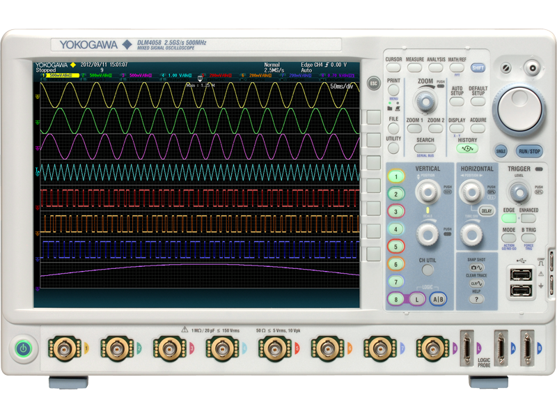

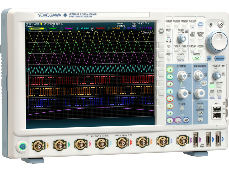


The DLM4000 is an eight-channel mixed-signal oscilloscope suitable to test and debugging applications in the embedded systems, power electronics, mechatronics, and automotive sectors. Available in both 350 MHz and 500 MHz models, the 2.5 GSa/sec DLM4000 features eight analog input channels. The eighth input channel features Flex MSO which converts to a 8-bit logic analyzer at the push of a button; add sixteen additional logic analyzer inputs as an option, for 24-bit logic analysis. Advanced measurement and analysis features such as power analysis and serial-bus analysis, digital filtering, user-defined math, and super-long record lengths (up to 250 Mega Points) make the DLM4000 a super powerful engineering tool. High-resolution 12.1-inch LCD display, compact landscape format, ergonomic and friendly user-interface make it easy to use.
The portable eight-channel DLM4000 is the daily instrument of choice

Superior Functionality
Motor control & inverter circuit development

Key to efficient and reliable high-performance electric motors is the modern inverter design, or ‘Intelligent Power Module’. Multi-channel, high-speed waveform measurement is an absolute necessity. Four channels are simply not enough. Boasting eight true analog inputs, the DLM4000 empowers today’s engineer with a convenient and comprehensive measurement system.
Electronic control unit & mechatronic test

Numerous I/O analog, digital, and serial-bus waveforms surrounding the Electronic Control Unit (ECU) must be measured. The DLM4000 offers ample channel-count and architecture to monitor eight analog channels and up to 24-bits of logic input while simultaneously performing protocol analysis such as UART, I²C, SPI, CAN, CAN FD, LIN, CXPI, PSI5 and FlexRay. The DLM4000 can speed up the R&D process when four channels are not enough.
Limitation of 4 ch MSO: The additional logic inputs of a four-channel MSO mixed-signal oscilloscope provides enough channels, but this method has a blind-spot. Digital waveform analysis using logic inputs alone cannot reveal anomalies such as voltage drift, noise, distortion or ringing, and measure risefall times. ECU testing requires stringent examination of all digital waveforms- and analog input channels are the best tool for the job.
Reliable triggering
When just a specific event or abnormal waveform needs to be captured, the flexible and reliable triggering of the DLM4000 is the solution. In addition to basic trigger functions such as Edge, State, and Pulse Width- Advanced trigger types are provided, including Edge OR between multiple channels, Serial Bus trigger in which A combination of two bus signals is possible, or an A and B combination of different trigger types.

Best in Class Deep Memory & Architecture
The two advantages of a long waveform memory are the abilities to capture for long periods of time and to maintain high sample rates. Thus achieving higher effective measuring bandwidths for all time base settings.
Measuring time = Memory length / Sample rate
With the maximum memory installed (/M3 option), in single shot mode, a 10 kHz signal lasting for more than one hour can be captured. The same memory can capture a 200 millisecond signal at a sampling rate of 1.25 GS/s.

Two fully independent zoom windows
Enabling two fully independent zoom windows allows users to analyze the cause and effect of abnormal behaviors over all input channels. Users can also view and compare the details and timing of different serial buses operating at different speeds.

History Function
The DLM4000 can capture and replay up to 50,000 individual acquisitions (/M3 option). These can be displayed one at a time or as an accumulation. Using the search and measurement functions, abnormal signals can therefore be quickly isolated, analyzed and precisely categorized without needing to carefully configure triggers to capture rare events.
History Search Function
Search up to 50,000 waveform history records based on detailed search parameters using the history search function.

Replay Function
Automatically play back, pause, fast forward, and rewind waveform history records.


Additional Option License for DLM4000
This is a license product for adding applicable optional features on to DLM4000 series on your own.
It is necessary to update main unit firmware in advance to V3.03 and above* in order to apply this license.
* Firmware version 3.70 or higher is required to apply -F9, -X1 licenses.
* Firmware version 4.70 or higher is required to apply -10, -11 licenses.
* Firmware version 5.01 or higher is required to apply -F4, -F6, -F7, -F8 licenses.
| Model | Suffix code | Description |
|---|---|---|
| 709820 | -G2 | User defined math |
| -G3 | Power supply analysis function | |
| -G4 | Power supply analysis function (includes G2) | |
| -F1 | UART trigger and analysis | |
| -F2 | I²C + SPI trigger and analysis | |
| -F3 | UART + I²C + SPI trigger and analysis | |
| -F4 | CAN + LIN trigger and analysis + CXPI analysis | |
| -F5 | FlexRay trigger and analysis | |
| -F6 | FlexRay + CAN + LIN trigger and analysis + CXPI analysis | |
| -F7 | CAN + CAN FD + LIN trigger and analysis + CXPI analysis | |
| -F8 | FlexRay + CAN + CAN FD + LIN trigger and analysis + CXPI analysis | |
| -F9 | SENT trigger and analysis | |
| -10 | PSI5 analysis | |
| -11 | SENT+PSI5 trigger and analysis | |
| -X1 | F4 -> F7 or F6 -> F8 (adds CAN FD) |
Power Supply Analysis Function (/G3,/G4 option)
The /G3 and /G4 options enable switching loss, joule integral (I2t), SOA (safe operating area), harmonics based on EN61000-3-2, and other power parameters to be measured and analyzed.
Switching loss analysis:
The switching loss of the voltage and current input waveforms can be computed (U(t) x (I(t)) over long time periods. The turn-on/off loss, the loss including the continuity loss, and the loss over many cycles of the 50 Hz/60 Hz power line can be calculated and analyzed.

Power Measurement
The DLM4000 can also be used as a power meter by providing automated measurement of power parameters for up to two pairs of voltage and current waveforms, such as the active power, apparent power and power factor. These values can be statistically processed and calculated.

Related Accessories
Differential probe PBDH0150 (701927)
DC to 150 MHz
1000 Vrms/ ±1400 Vpeak

Differential probe (701926)
DC to 50 MHz
5000 Vrms/7000 Vpeak

Current probe PBC100/PBC050 (701928/701929)
DC to 100 MHz (701928)
DC to 50 MHz (701929)
30 Arms

Deskew correction signal source (701936)

User defined math (/G2, /G4 option)
Equations can be arbitrarily created using a suite of operators such as trigonometric and logarithmic operators, integration and differentiation, pulse width operators, phase measurement and digital to analog conversion.

Logic signal analysis (/L16 option)
The flexible MSO inputs are included as standard. This enables the DLM4000 to be converted to a 7 analog and 8 digital input MSO. With the /L16 option, up to 24 logic signals can be measured. Bus/State display and optional DA calculation function, which is useful for evaluating AD/DA converters, are also provided.

Serial bus analysis function
UART (RS232)/ I²C/ SPI/ CAN/ CAN FD/ LIN/ FlexRay/ SENT/ PSI5/ CXPI
Dedicated trigger and analysis options are available for various serial buses of both in-vehicle and embedded systems. A wide variety of trigger combinations can be set, including ID and Data combinations, which can also be combined with conventional edge triggers. Trigger functions of some of the serial buses are not supported. Simultaneously display the physical layer waveforms and the digital data.
Serial bus auto-setup saves time
An intelligent serial bus auto-setup detects bit-rate and voltage threshold automatically and enables the DLM4000 to be quickly configured.
Up to 4 buses simultaneously
Analysis can be performed at high speed simultaneously on up to four different buses operating at different speeds. This is enhanced by the extensive search facilities, allowing the user to look for specific data in the very long memory. The dual-zoom facility means that different buses can be viewed and debugged alongside each other.

Related Accessories
Differential probe PBDH1000 (701924)
DC to 1.0 GHz bandwidth 1 MΩ, approximately 1.1 pF
Maximum differential input voltage range: ±25 V

Differential probe (701920)
DC to 500 MHz bandwidth
100 kΩ, approximately 2.5 pF
Maximum differential input voltage range ±12 V

Logic probe PBL100/PBL250 (701988/701989)
100 MHz/250 MHz toggle frequency 1 MΩ, 10 pF/100 kΩ, 3pF

Broad connectivity and easy control

PC connectivity and software tools

Complement complex measurement tasks using a comprehensive suite of software tools.

 |
Reduced energy, emission of CO2, NOx and SOx about 25% compared to the previous model. Results of Life Cycle Assessment |
- Released new firmware version 5.01.
- Added CXPI analysis option. (/F4,/F6,/F7,/F8)
- Released new firmware version 4.72.
- Increased the maximum number of trend display from 1 to 4 in the SENT analysis function. (/F9,/F10)
- New features added.
- /F10 (PSI5 analysis option)
- /F11 (SENT+PSI5 trigger and analysis option)
- Released new firmware version 4.43.
- /F7, /F8 CAN FD analysis option revised to comply with ISO standard.
| Model | Description |
|---|---|
| DLM4038 | DLM4038 350 MHz Mixed Signal Oscilloscope 8-channel 8-bit |
| DLM4058 | DLM4058 500 MHz Mixed Signal Oscilloscope 8-channel 8 bit |

701944 High Voltage Passive Probe 1000Vrms / 400 MHz
- 701944 High Voltage Passive Probe 1000Vrms / 400 MHz
- For DL1700, DLM2000-6000, DL6000, DL9000, SB5000 series

701939 Passive Probe 600V / 500 MHz
- 701939 Passive Probe 600V / 500 MHz - Current Probe
- 500 MHz, 10:1, 600 V (DC + ACpeak) CAT II, 1.3 m
- For DLM2000, DLM4000, DL6000, DLM6000 series

701945 High Voltage Passive Probe 1000Vrms / 250 MHz
- 3m High Voltage Probe (oscilloscope)
- DC to 250 MHz bandwidth
- 100:1 attenuation
- Max Input 1000 Vrms CAT II 4000 V transient over-voltage CAT O

701946 Miniature Passive Probe 400V / 500 MHz
500 MHz, 10:1, 400 Vrms/1250 Vpeak CAT O 300 Vrms CAT II, 1.2 m
For DLM2000, DLM4000, DL6000, DLM6000 series

702906 Passive Probe 1000V / 200 MHz
200 MHz, 10:1, ±1000 V (DC + ACpeak) CAT II, 2.5 m,Wide operating temperature range (−40 to +85°C)
For DLM2000, DLM4000 series.

700924 Differential Probe 1400V / 100 MHz
- Differential oscilloscope probe
- 100 MHz
- ±1400 V (DC + ACpeak) at 1000:1
- Power: Internal battery or probe power supply
- Works with Oscilloscopes, ScopeCorders

700925 Differential Probe 500V / 15 MHz
15 MHz, 100:1/10:1, Max. Differential Voltage: ±500 V (DC + ACpeak) or 350 Vrms at 100:1 attenuation, Probe Power: Internal battery or probe power supply Work with Oscilloscopes, ScopeCorders

701920 Differential Probe 12V / 500 MHz
500 MHz, 10:1, Max. Differential Voltage: ±12 V (DC + ACpeak), Probe Power: probe power supply Work with 50 Ω input system oscilloscope

701921 Differential Probe 700V / 100 MHz
100 MHz, 100:1/10:1, Max. Differential Voltage: ±700 V (DC + ACpeak) at 100:1 attenuation, Probe Power: Internal battery or probe power supply

701922 Differential Probe 20V / 200 MHz
200 MHz, 10:1, Max. Differential Voltage: ±20 V (DC + ACpeak), Probe Power: probe power supply Work with 50 Ω input system oscilloscope

701924 Differential Probe 25V / 1 GHz
- 701924 Differential Probe
- 1 GHz, 50:1, Max. Differential Voltage: ±25 V (DC + ACpeak), Probe Power: dedicated probe interface

701926 Differential Probe 7000V / 50 MHz
50 MHz, 1000:1/100:1, Max. Differential Voltage: 5000 Vrms/7000 Vpeak (1000:1), Probe Power: Internal battery or probe power supply B9852MJ power cable is bundled Work with Oscilloscopes, ScopeCorders

701927 Differential Probe 1400V / 150 MHz
- 701927 Isolated Differential Probe
- 150 MHz
- Max. Differential Voltage: ±1400 V (DC + ACpeak) at 500:1
- Probe Power: dedicated probe interface For DLM, DL, and SB5000 series

700939 Active FET Probe 10V / 900 MHz
- 700939 Active FET Probe
- 900 MHz Active FET Probe Circuit
- 10:1, ±10 V (DC + ACpeak) FET Input Active Probe
- 1.5 m

701917 Current Probe 50 MHz / 5 ARMS
- 701917 oscilloscope current probe
- Frequency bandwidth: DC to 50 MHz
- Maximum continuous input range: 5 Arms
- Functions with Digital Oscilloscopes, ScopeCorders, other waveform measuring instruments

701918 Current Probe 120 MHz / 5 ARMS
- Yokogawa 701918 Current Probe
- Frequency bandwidth: DC to 120 MHz
- Maximum continuous input range: 5 Arms
- Functions with Digital Oscilloscopes, ScopeCorders, other waveform measuring instruments

701928 Current Probe 100 MHz / 30 ARMS
- 701928 scope current probe
- Front-end powered
- Recognized automatically
- Adjust zero position from operation of DLM2000, DLM3000, DLM4000, DL6000/DLM6000, DL9000/DLM9000. SB5000

701929 Current Probe 50 MHz / 30 ARMS
- 701929 Current Probe 50 MHz / 30 ARMS
- Front-end powered
- Auto-recognized
- DLM2000-4000, DL/DLM6000, DL/DLM9000, SB5000

701930 Current Probe 10 MHz / 150 ARMS
- 701930 Current Probe 10 MHz / 150 ARMS
- Powered by Yokogawa Digital Oscilloscopes, Scopecorders or external power supply

701931 Current Probe 2 MHz / 500 ARMS
- 701931 Current Probe 2 MHz / 500 ARMS
- Powered by Yokogawa Digital Oscilloscopes, Scopecorders or external power supply

701934 External Probe Power Supply
- 701934 External Probe Power Supply
- Power supply for current probes, FET probes, and differential probes
- Supplies power for up to four probes, including large current probes

B9852MJ Power Cable for Differential Probes
- B9852MJ power probe extension cable
- Supplies power to 700924, 700925, and 701921 differential probes from the DL probe power connectors
- Required on DL unit
- Only works with newer probes

701936 Deskew correction signal source
- 701936 Deskew Correction Signal Source
- Improve switching-loss measurements by deskewing
- Accommodates both clamp-on current probes and through-type ‘CT' Current Transformers


B9852ES Logic Probe IC Pin Clips
- B9852ES Logic Probe IC Pin Clips
- Attach to tips of logic probe (701988 or 701989) or mini-clips (B9852CR)
- Clip contiguous 0.5-mm pitch terminals
- 10 clips included


700971 Mini clip converter
A clip set designed for 701937, 701938, 701939, 701943 (PB500) and 700939


701901 BNC to Safety Banana 1.8m Cable, 1:1
- 701901 BNC to Safety Banana 1.8m Cable, 1:1
- 1000 Vrms-CAT II, 1.8 m long
- Safety BNC(male) to safety banana(female)
- 701959, 701954, 758921, 758922, 758929

701906 Long Test Clip
Set contains one black and one red clip
1000 Vrms-CAT II
2 pieces (red and black) in 1 set
Connected to the 758933, 758917, or 701901
Length: 0.3m
Applicable for DL750/DL750P, SL1000, SL1400

701948 Extension Clip Accessories
Connected to the 700929, 701947
Maximum input voltage: 1,000V (DC + ACpeak)
Length: 0.26m/0.3m/0.4m
Applicable for DL750/DL750P, SL1000, SL1400

701954 Large Alligator Clip (dolphin type)
Set contains one black and one red clip.
1000 Vrms-CAT II.

701975 50 Ω DC block for 701974
This DC block can be used to remove the DC component from an incoming signal. Use this block if you want to remove bias voltage from reaching the PBL5000 probe.

758921 Fork terminal adapter
- 758921 Fork Terminal Adapters
- For fitting a 4mm banana plug to a fork terminal
- One black and one red clip
- 1000 Vrms-CAT II

758922 Small Alligator-Clip Adapter 300V
Rated at 300 V. Attaches to the 758917 test leads. Sold in pairs.

758929 Large Alligator Clip Adapter 1000V
- Yokogawa 758929 Alligator Clip Adapter
- Rated at 1000V
- Attaches to 758917 test leads
- Sold in pairs black/red

758917 DMM Measurement Lead Set
- Set of 0.8m long red and black multimeter test leads
- Used in combination with a pair of optional 758922 or 758929 alligator-clip adapters
- 1000 Vrms, 32 Arms CAT II

761953 Safety Terminal Adapter Set
Two adapters to a set for 5 A current
(screw-fastened type using B9317WD)

B9852CR Mini Clip Passive Probe Tip
A clip set designed for the 700988, 700960 and 701940 probes.

B9852HF Basic accessories set for the 701941 probe
The B9852HF contains the following eleven(11) kinds of accessories: Insulation cap, IC cap, BNC adapter, Rigid tip, Spring tip (Ø: 0.80 mm), Spring tip (Ø: 0.38 mm), Ground spring, Adjustment tool, Pincher tip, Standard ground lead, Color coding rings. PBL5000.

366924 BNC to BNC 1m Cable
- 366924 BNC to BNC cable for oscilloscope
- 1m BNC wire
- Simultaneous measurement with 2 units
- Input external trigger signal

366973 Go/No-Go Cable
This cable is used to connect an external device, however, do not use this cable for purposes other than DL750/1600/1700/1700E/7400 GO/NO-GO judgement.

366923 BNC to T Adapter
T-adapter for BNC connectors. Use for circuits having voltage levels no greater than 42 V.

366925 BNC to BNC 2m Cable
BNC-BNC 2m. For connection to simultaneously measurement with 2 units, or for input external trigger signal.

366945 Printed circuit board adapter
For 701937, 701938, 701939, 701943 (PB500) and 700939.
Quantity of 1 unit: 10

366926 BNC to Alligator 1m Cable, 1:1
- 1 m long BNC to alligator clip cable
- Only for circuits with voltage levels no greater than 42 V
- Applicable for DL750/DL750P, SL1000 & SL1400

366946 Solder-in adapter
For 701937,701938, 701939, 701943 (PB500) and 700939 Standard accessories include: Adapter, red wire (3), black wire (3)

366961 Banana to Alligator 1.2m Cable, 1:1
A subassembly of 1.2 m long test leads with alligator-clip adapters.
Use only for circuits having voltage levels no greater than 42 V.
Applicable for SL1000 & SL1400.

758924 BNC to Banana Conversion Adapter
For conversion between BNC and female banana plug
Applicable for DL750/DL750P, SL1000 & SL1400.


366921 BNC to Banana-Jack (Female) Adapter 42V
BNC-Banana-jack (female) adapter. Use for circuits having voltage levels no greater than 42 V.
B8099NM 4mm conversion adapter
For 702902, 702906

366922 BNC to Banana (Male) Adapter
Banana-plug (male)-BNC adapter. Use for circuits having voltage levels no greater than 42 V.

701919 Probe Stand
- 701919 oscilloscope probe stand
- Flexible arm, heavy base to hold and stabilize 8-13mm probes
- Can simplify circuit board testing


751512 Banana (Male) to Binding Post Adapter
Safety-terminal-binding-post adapter. Use for circuits having voltage levels no greater than 42 V.

701968 Soft carrying case for DLM4000/DLM5000
Three pockets are provided for storing accessories and the user’s manual.

701969 Rack mount kit for DLM4000/DLM5000/DLM5000HD
- Rack mount kit for DLM4000/DLM5000/DLM5000HD Mixed Signal Oscilloscope series
- EIA/JIS standard compliant

- Construction and verification of SENT communication system
- Accurate, reliable data transmission at low cost


While accurate rise time measurements have become easier to make, it remains, nonetheless, quite easy to overlook error contributions due to not only the oscilloscope but also the probe. And, while the error contributed by a scope's finite step-response (rise time) is often accounted for, that contributed by the probe is often overlooked.

Frequency to Voltage Conversion Problem: A transducer produces a sine-wave output dependant on the voltage-input; here is how to decode that output with a scope or a ScopeCorder. For 3kV input, the transducer ...
The free software DL-GATE can be used for the following products only:DL1700E seriesDL7400 series (firmware version after 1.32)DL1600 series (firmware version after 1.13)DL750 series (firmware version after ...

This comprehensive training module covers the following topics:
- Introduction & Product Familiarization
- Basic Understanding and Operating Features
- Advanced Analysis Features
- Communication Features

This training module covers the following topics:
- Introduction & Installation
- Basics of Xviewer
- Advanced features
- Video Demonstrations
Brochures
- DLM4000 Series Mixed Signal Oscilloscope (12.2 MB)
Instruction Manuals
- DLM4000 Series Mixed Signal Oscilloscope Features Guide (11.6 MB)
- DLM4000 Series Mixed Signal Oscilloscope USER'S MANUAL (16.7 MB)
- DLM4000 Series Mixed Signal Oscilloscope Getting Started Guide (7.2 MB)
- DLM4000 Series Mixed Signal Oscilloscope Communication Interface USER'S MANUAL (5.0 MB)
- Model 709820 Additional Option License for the DLM4000 Series User's Manual (270 KB)
- Model 701990 Sample Program for the DL Series Digital OscilloscopeRead this first. (193 KB)
Specifications
- Result of Life Cycle Assesment for DLM4000 (179 KB)
- SENT Protocol Debug & Analysis (1.0 MB)
Software
- Xviewer 701992 / XviewerLITE
- Xwirepuller
- MATLAB WDF Access Toolbox
- Symbol Editor
- Mask Pattern Editor
- Binary Data File Converter
- DL-Term
- Communication Sample Programs
- TMCTL
- Yokogawa WDF DataPlugin ( NATIONAL INSTRUMENTS Web Page )
- USB Drivers
- LabVIEW Drivers for DLM4000 Series ( NATIONAL INSTRUMENTS Web Page )
Firmware
Drawings
- DLM4000 Mixed Signal Oscilloscope (1005 KB)
Product Overviews

Yokogawa has launched a new range of high frequency, high voltage differential oscilloscope probes, combining proven features of its existing probes with new capabilities.
Yokogawa has added CXPI serial bus analysis to the range of options available on the company’s DLM2000 and DLM4000 Series mixed signal oscilloscopes.

