701275 Accelerometer & Voltage Module with AAF

The Yokogawa 701275 is a voltage and accelerometer input module for vibration and dynamic signal analysis on the ScopeCorder platform. It provides built-in sensor bias for direct connection of amplifier type accelerometers and supports 100 kS per second sampling, 16-bit resolution, and wide bandwidth measurement.
Key Features
- Voltage and Acceleration Measurement in One Module: Supports both voltage and acceleration inputs that can be switched per channel, allowing flexible use for vibration, shock, and general analog measurements.
- Wide Bandwidth, High-Resolution Acquisition: Supports DC to 40 kHz bandwidth for voltage and 0.4 Hz to 40 kHz for acceleration, with built-in anti-aliasing filters and isolated 16-bit inputs sampling at 100 kS per second for clean time- and frequency-domain analysis of vibration and transient events.
- Integrated Sensor Bias Supply: Provides built-in constant current excitation of 4 mA at 22 V, enabling direct connection of built-in amplifier type acceleration sensors without the need for an external power supply or charge amplifier.
- Broad Sensor Compatibility: Supports built-in amplifier type accelerometers from major manufacturers such as Kistler1 (Piezotron™), PCB1 (ICP™), and Endevco1 (Isotron™). High-impedance acceleration sensors can also be used with external charge converters.
1: Registered trademarks of their respective companies.

| Item | Specifications | |||||||||||||||||||||||||||||||||||||||||||||
|---|---|---|---|---|---|---|---|---|---|---|---|---|---|---|---|---|---|---|---|---|---|---|---|---|---|---|---|---|---|---|---|---|---|---|---|---|---|---|---|---|---|---|---|---|---|---|
| Standard operating conditions | Temperature: 23 ±5 °C Humidity: 20 to 80 % RH After a 30 minute warm-up and after calibration |
|||||||||||||||||||||||||||||||||||||||||||||
| Effective measurement range | 20 div (display range: 10 div) | |||||||||||||||||||||||||||||||||||||||||||||
| Number of input channels | 2 | |||||||||||||||||||||||||||||||||||||||||||||
| Input coupling settings | AC, DC, ACCL (acceleration), and GND | |||||||||||||||||||||||||||||||||||||||||||||
| Maximum sample rate | 100 kS/s | |||||||||||||||||||||||||||||||||||||||||||||
| Input type | Isolated unbalanced | |||||||||||||||||||||||||||||||||||||||||||||
| Frequency characteristics1 (−3 dB point when a sine wave of amplitude ±3 div is applied) | Waveform measurement mode: DC to 40 kHz Acceleration measurement mode: 0.4 Hz to 40 kHz |
|||||||||||||||||||||||||||||||||||||||||||||
| Voltage scale setting | 5 mV/div to 10 V/div (1-2-5 steps) (when using 1:1 probe factor) Acceleration (±5 V = ×1 range): ×0.1 to ×1 to ×100 (1-2-5 steps) |
|||||||||||||||||||||||||||||||||||||||||||||
| Maximum input voltage (at a frequency of 1 kHz or less) | 42 V (DC+ACpeak)2 | |||||||||||||||||||||||||||||||||||||||||||||
| Maximum rated voltage to ground – between input and case and between inputs (at a frequency of 1 kHz or less) | Working voltage of safety standard 42 V (DC+ACpeak) (CAT II, 30 Vrms)3 |
|||||||||||||||||||||||||||||||||||||||||||||
| Vertical (voltage) axis accuracy DC accuracy1 | Waveform measurement mode DC accuracy: ±(0.25 % of 10 div) Acceleration measurement mode: ±(0.5 % of 10 div) at 1 kHz |
|||||||||||||||||||||||||||||||||||||||||||||
| Input connector | BNC connector (metal type) | |||||||||||||||||||||||||||||||||||||||||||||
| Input impedance | 1 MΩ ±1 %, approx. 35 pF | |||||||||||||||||||||||||||||||||||||||||||||
| −3 dB point when AC coupled | 0.4 Hz or less (0.04 Hz or less when the 701940 is in use) (typical value4) | |||||||||||||||||||||||||||||||||||||||||||||
| Common mode rejection ratio | 80 dB (50/60 Hz) or more (typical value4) | |||||||||||||||||||||||||||||||||||||||||||||
| Residual noise level (input section shorted) | ±100 µV or ±0.01 div whichever is greater (typical value4) | |||||||||||||||||||||||||||||||||||||||||||||
| A/D converter resolution | 16 bits (2400 LSB/div) | |||||||||||||||||||||||||||||||||||||||||||||
| Temperature coefficient | When in waveform measurement mode (excluding AUTO filter) Zero point: ±(0.02 % of 10 div)/°C (typical value4) Gain: ±0.02%/°C (typical value4) |
|||||||||||||||||||||||||||||||||||||||||||||
| Bandwidth limit | Select from Full, Auto, 4 kHz, 400 Hz, 40 Hz Cutoff characteristics: –12 dB/OCT (typical value,4 setting other than AUTO) Cutoff frequency (fc) when set to AUTO
|
|||||||||||||||||||||||||||||||||||||||||||||
| Probe attenuation settings | Voltage probe: 1:1, 2:1, 5:1, 10:1, 20:1, 50:1, 100:1, 200:1, 500:1, 1000:1, 2000:1, 5000:1, 10 k:1, 20 k:1, 50 k:1 Current probe: 0.1 A:1 V, 0.2 A:1 V, 0.5 A:1 V, 1 A:1 V, 2 A:1 V, 5 A:1 V, 10 A:1 V, 20 A:1 V, 50 A:1 V, 100 A:1 V, 200 A:1 V, 250 A:1 V, 400 A:1 V, 500 A:1 V, 1 kA:1 V, 2 kA:1 V, 5 kA:1 V, 10 kA:1 V, 20 kA:1 V, 50 kA:1 V |
|||||||||||||||||||||||||||||||||||||||||||||
| Compliant voltage probe | 701940 (17 to 46 pF) | |||||||||||||||||||||||||||||||||||||||||||||
| Sensor supply current (voltage) | OFF/4 mA ±10 % (approx. 22 VDC) | |||||||||||||||||||||||||||||||||||||||||||||
| Applicable acceleration sensor | Built-in amplifier type Kistler Instrument Corporation: Piezotron, PCB Piezotronics Incorporated: ICP, ENDEVCO Corporation: ISOTRON, etc. |
|||||||||||||||||||||||||||||||||||||||||||||
| Table of cutoff frequency characteristics of the anti-aliasing filter (AAF) | When the filter is set to Auto, the anti-aliasing filter and low-pass filter are automatically set according to the sample rate.
|
|||||||||||||||||||||||||||||||||||||||||||||
| Wiring / measurement points |
|

1. Value measured under standard operating conditions.
4. Typical values represent typical or average values. They are not strictly warranted.

DL950 ScopeCorder
Capture and analyze a wide variety of electromechanical signals and serial buses. High sample rate, long recording times, advanced triggers, and real-time analysis.

DL350 Portable ScopeCorder
A compact, battery-powered, touch screen instrument you can take into the field featuring the measurement and recording capabilities you need for maintenance and troubleshooting.
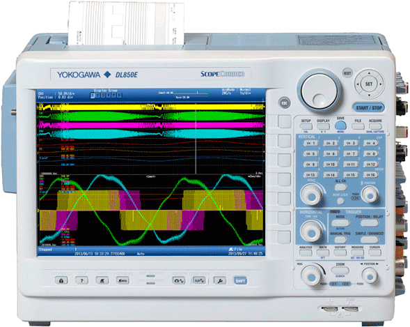
DL850E/DL850EV ScopeCorder
An all-in-one electromechanical measurement system offering the deepest measurement and analysis features to turn data into insights.

DL850/DL850V ScopeCorder
Combining the capabilities of an Oscilloscope and the characteristics of a Data Acquisition Recorder, the Yokogawa Scopecorder is a versatile tool for engineers making measurements in the industrial, transportation and energy sectors.

SL1000 High-Speed Data Acquisition Unit
Predecessor to SL2000. A PC-based ScopeCorder system capable of synchronizing multiple chassis.

How can I capture data from motion sensors synchronized with other analog data? The Yokogawa ScopeCorder series of instruments feature input modules and functions to make this possible.
Brochures
Drawings
How-tos

In this video we demonstrate the GPS data logging capability of the DL350 Portable ScopeCorder. Recording Position, Velocity, and Altitude simultaneously with accelerometers or other analog inputs is simple with the DL350's built-in features.

