WT3000E High Accuracy Power Analyzer (DISCONTINUED)


The WT3000E provides engineers with a solution for verifying product efficiency and compliance to IEC harmonic and flicker standards. The WT3000E is ideal for the design and testing of appliances, solar inverters, motor drives, lighting systems, uninterruptible power supplies, transformer testing, aircraft power systems, and other power conversion devices.
With a basic power accuracy of ±0.04% (total), DC and 0.1 Hz-1 MHz measurement bandwidths, and up to four input elements, the WT3000E provides high-accuracy measurement of I/O efficiency.
- Basic power accuracy: 0.04%(total)
- Both 2 A and 30 A input elements can be installed in a single unit
- The latest IEC61000-3-2 and IEC61000-3-12: Harmonic measurement
- The latest IEC61000-3-3 and IEC61000-3-11: Voltage fluctuation / flicker measurement
- Store function: 50 ms data storing interval
- Advanced computation function: Waveform computation, FFT analysis, waveform sampling data saving
- Multiple computer interfaces supported: GP-IB, Ethernet, RS-232 and USB
Key Specifications
-
High accuracy and wide frequency range:
Basic power accuracy:
±(0.01% of reading + 0.03% of range)
Frequency range:
DC, 0.1 Hz to 1 MHz -
Low Power Factor Error:
Power factor error when cos ø=0:
0.03% of S where
S is the reading value of apparent power
ø is the phase angle between voltage and current -
Current Range:
Direct Input:
0.5 / 1 /2 / 5 / 10 / 20 / 30 [A] or 5 / 10 / 20 / 50 / 100 / 200 / 500 [mA], 1 / 2 [A] *
* 2A and 30A input elements can be installed together in one unit.
External Input:
50m / 100m / 200m / 500m / 1 / 2 / 5 / 10 [V]
- Voltage Range and current range are for crest factor 3
- 1000 [Vrms] Continuous maximum common mode voltage (50/60 Hz)
- Data Update rate: 50 ms to 20 sec
- Effective input range: 1% to 130%
- Simultaneous measurement with 2 Units
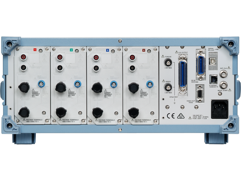
Rear Panel

| Standard Features | Optional Features |
|
|
Characteristics
Example of basic characteristics showing the WT3000E’s high precision and excellent stability

Delta Calculation Function
Checking phase voltage when you measure line to line voltage
This function allows you to calculate individual phase voltages from the line voltage measured in a three-phase, three-wire (3V3A) system. R-S line voltage can be calculated in systems measured from a three-phase, three-wire method (using two elements). This is useful when you want to determine the phase voltage in motors and other items under test with no neutral lines. Line to line voltage and phase current (measurements equivalent to 3V3A) can be estimated in systems not measured from a three-phase, three-wire configuration (using two elements).

Cycle-by-cycle Measurement Function
When you have fluctuating data or during motor evaluation *you may need to capture rapidly changing phenomena such as during load fluctuations in a motor. These tasks can be handled effectively with the cycle-by-cycle measurement function. The function takes measurements of parameters such as voltage, current, and active power for each cycle, then lists the data on screen in a time series. Up to 3000 data (measurements of signals from 0.1 Hz to 1000 Hz) can be saved in CSV format.
* Requires the motor evaluation option (/MTR)


Range settings using direct key input
Simpler range settings
 The range indicator on the WT3000E is an easy-to-read seven-segment green LED, so the set range can be monitored at all times. The range can easily be switched using the up and down arrows next to the display.
Intuitive control using cursor keys
 Easier cursor navigation and numerical settings
 Easier cursor navigation and numerical settings
Cursor keys can be used to move the screen cursor in four different directions, so it is easy and intuitive to set scaling factor and other settings.
Using item pages to set display preferences
Item pages make it easy to set the data you want to view for each experiment

The WT3000E has nine item pages for displaying measurement values. Once you set the measurement parameters you want displayed on a particular item page, you can easily switch between entire groups of displayed parameters. For example, the following settings make it easy to switch and compare data:
Page 1: Voltage, current, active power, and current frequency for input element 1
Page 2: Voltage, current, active power, and current frequency for input element 2
Page 3: Voltages for input elements 1, 2, 3, and 4
Page 4: Currents for input elements 1, 2, 3, and 4
Page 5: Power for input elements 1, 2, 3, and 4
A Variety of display formats
Formats for viewing waveforms as well as numerical values
 The WT3000E lets you display input signal waveforms in addition to numerical value data. This means you don't need to connect a special waveform analyzer just to check signal waveforms. 1
In addition, the optional advanced calculation function lets you display vectors and bar graphs for enhanced visual presentation. The information display shows voltage range, current range, filter, and scaling value altogether, making it easy to check your settings. 2
1 Waveforms up to approximately 10 kHz can be displayed accurately.
2 More than two sets of same type input elements are required.
50ms data update intervals
High-speed measurement to capture rapid data fluctuations
The fast update rate allows you to precisely capture rapidly changing transient states in the measurement subject.
* The WT3000E switches between two different calculation systems depending on the data update interval. See other page for details.
Compensation functions
For increased measurement precision
The WT3000E has compensation functions for high-precision measurements. These functions can compensate for instrument-related losses resulting from the power meter’s internal impedance as well as losses related to wiring during measurement with two power meters. The following compensation functions are provided to compensate for instrument-related losses:
- Efficiency compensation: This function compensates for instrument-related losses occurring during efficiency calculation.
- Wiring compensation: This function compensates for instrument-related losses caused by wiring.
When measurements are performed using two power meters with three-phase, three-wire wiring, errors may occur if current flows to the middle wire (or if there is a leakage current). The WT3000E has a function to compensate for such errors. Even when measurements are performed with two power meters (requires measurement with three-phase three-wire (3V3A) wiring), the current flowing to the middle wire is calculated, and a corresponding correction value can be added to the power measurement. This improves the accuracy of power measurements.
User-defined functions
A way to add user-defined measurement parameters
As many as twenty user-defined formulas can be set in the WT3000E. These equations can be used to calculate various parameters, such as mean active power (see "A variety of integration functions" below).
Efficiency calculation function
An easier way to input efficiency calculation formulas
This function can be used to set up to four efficiency calculation formulas.
A Variety of integration functions
Apparent power integration and reactive power integration
- Active power, current, apparent power, reactive power
In addition to the active power integration function (WP) and current integration function (q) included in earlier models, the WT3000E also has a new apparent power integration function (WS) and reactive power integration function (WQ). - A wide effective input range for high-precision integration
The WT3000E has a wide effective input range, from 1% to 130% of the measurement range. This enables higher-precision integration measurements on measurement subjects with current values that fluctuate widely from large currents down to faint currents in the standby state. - Mean active power (using user-defined settings)
Mean active power can be calculated over an integration interval. This feature is useful for evaluating the power consumed by intermittent-control instruments in which the power value fluctuates.

Supports Crest Factor 6
The crest factor is the ratio of the waveform peak value and the RMS value. |
 |
When checking the measurable crest factor of our power measuring instruments, please refer to the following equation.

* However, the peak value of the measured signal must be less than or equal to the continuous maximum allowed input.
* The crest factor on a power meter is specified by how many times the peak input value is allowed relative to rated input value. Even if some measured signals exist whose crest factors are larger than the specifications of the instrument (the crest factor standard at the rated input), you can measure signals having crest factors larger than the specifications by setting a measurement range that is large relative to the measured signal. For example, even if you set CF = 3, CF5 or higher measurements are possible as long as the measured value (RMS) is 60% or less than the measuring range. Also, for a setting of CF = 3, measurements of CF = 300 are possible with the minimum effective input (1% of measuring range).
Store Function
Voltage, current, power, and other measured data can be stored to the unit's approximately thirty megabytes of internal memory. These data can be saved in binary or ASCII format on a PC card or USB memory*.
* The USB port (for peripherals) comes with the /C5 option.

Each measured item can be stored at every data update interval. You can specify to store only the desired measured items, thus saving memory.
 Files saved in ASCII format can be opened in general-purpose applications such as Excel allowing display of data in graphs.
* Please note that data saved in binary format can only be manipulated using dedicated software to be made available by Yokogawa.
 Excel Example |
Options
A wide variety of optional functions make it easy to perform sophisticated power evaluations.
When you purchase a WT3000E from Yokogawa, you can select just the options you need. This approach lets you maximize performance at a lower cost.
Advanced Calculation Function (/G6)
The Advanced Calculation Function provides for wide bandwidth harmonic measurement, IEC compliant harmonic measurement (requires harmonic measurement software), FFT calculation, waveform calculation functions, and saving of waveform sampling data.
Wide Bandwidth Harmonic Measurement Mode
Harmonic measurement for a frequency range of 0.1 Hz – 2.6 kHz
Enables harmonic measurement over wide bandwidths. Supports measurement of harmonic signals beyond those of the harmonic measurement function in normal measurement mode. This option allows for harmonic analysis on waveforms with a fundamental frequency range of 0.1 Hz–2.6 kHz (*1). You can measure up to the 50th order harmonic at 1 kHz fundamental.(*2).
*1 0.1–10 Hz using an external sampling clock.
*2 Harmonic measurement of up to the 20th order possible in the 1 kHz to 2.6 kHz range.
Harmonic Measurement Function
Harmonic and normal power parameters measurement at same time
This function enables simultaneous measurement of normal and harmonic data, which was not possible with previous Yokogawa models. With the WT3000E you can simultaneously confirm total voltage and current as well as the distortion factor and fundamental wave without switching modes, this allows for more accurate and efficient measurement of the power supply quality, the fundamental wave of motor drive voltage, and other factors.
IEC Harmonic Measurement Mode
Perform tests conforming to international standards
The IEC harmonic measurement mode meets the window width requirement of the latest IEC harmonic standard (10 cycles of 50 Hz and 12 cycles of 60 Hz). Also, this mode allows users to use the 761922 harmonic measurement software to perform tests conforming to IEC 61000-3-2 and IEC61000-3-12.
* These modes cannot be used at the same time.
FFT Calculation Mode
More detailed frequency analysis than with the harmonic measurement mode.
Two FFT calculations can be performed simultaneously on waveform data of measured voltage and current. You can select a resolution for FFT of 1 Hz or 10 Hz. FFT analysis of up to 100 kHz can be performed.
Waveform Calculation Mode
Monitoring of instantaneous power waveforms
Up to two waveform calculations and other Waveform Calculation functions can be used at once. If you create a formula that multiplies voltage and current waveforms, you can confirm an instantaneous power waveform on screen. Waveform Calculation data can be saved in CSV or WVF format.
Waveform Sampling Data Saving Function
Save detailed waveform data for confirmation
All captured voltage and current waveform data (200 kS/s), calculated wave-forms, and FFT calculated waveforms can be saved. You can choose to save in CSV or WVF format, and to save to PC card or USB memory (/C5 option).
Motor Evaluation Option (/MTR)
 Calculation of motor and total efficiency
In addition to the functions of the standard version, the new models offer powerful motor/inverter evaluation functions- Voltage, current, and power measurement with torque and speed input
Measures torque meter and speed sensor output (analog or pulse output), and allows calculation of torque, revolution speed, mechanical power, synchronous speed, slip, motor efficiency, and total efficiency in a single unit.

Added Frequency Measurement (/FQ)
Check the frequencies of all inputs
In addition to the standard two channels of frequency measurement, a six-channel frequency measurement option is also available. This option provides frequency measurement of voltage and current on all eight channels (with input elements 1 through 4 installed). This is necessary when you want to measure voltage and current frequency from the instrument’s I/O as well as voltage and current frequencies of multiple items under test at the same time.
D/A Output (/DA)
Output measurement values as analog signals to other devices
- 20 channels
Measured values can be output as ±5V 5V FS DC voltages from the D/A output connector on the rear panel. Measured parameters can be output on up to twenty channels simultaneously. Even with four input elements installed, you can send up to five types of data per element to D/A output. - D/A zoom
Normally the D/A output function outputs DC voltage scaled to a range of -5V to 5V* with respect to the measurement range. For this reason, it may not be possible to observe fluctuations in a nearly constant signal if the D/A output is set to go to ±5V at the measurement range rated value. One case in which this could happen is when a 100V measurement voltage fluctuates in the range of ±3V.
The WT3000E has a D/A zoom function to solve such problems. This function allows the any input signal range to be scaled to between -5V and 5V* in the D/A output as Upper and Lower ranges. This makes it possible to enlarge input signal fluctuations for observation using a recorder or logger.
* The range is 0V to 5V for some functions, such as frequency measurement
Built-in printer(/B5)
Output graphics at the touch of a button
 The optional built-in printer is installed on the front side of the WT3000E, so it is easy to use even if the WT3000E is mounted on a rack. The printer can be used to print data and waveform memos.
Auto Print Function
The Auto Print function allows you to set a time interval at which measured values are automatically printed on the built-in printer. You can also set a start and stop time in order to record data over a desired time period. You can also specify to print only the desired measured items.
VGA output (/V1)
Video output for viewing on a larger screen
The VGA port can be used to connect an external monitor in order to view numerical value data and waveforms on a larger screen. This capability is useful if you want to simultaneously check large amounts of data on a separate screen, or view data in a separate location.
Serial (RS-232) (/C2)
USB Port for Peripherals (/C5)
 A USB port for peripherals with type A connectors can be included with the WT. The various kinds of data stored in the main unit such as voltage, current, and power, can be saved in binary or ASCII format on a peripheral such as a USB memory. You can also connect a keyboard for easy input of user-defined math expressions.
USB Port for Connection to PC (/C12)
The USB port (type B connector) on the rear panel of the WT3000E allows data communications with a PC¹. Also, instruments with this option installed can be used in conjunction with the communication functions of PC application software for data acquisition via USB².
- USB driver required for USB communications. A USB driver is available for download from our Web site.
- USB cable for connection to PC not included.
* USB stands for universal serial bus. USB is a standard designed to provide connectivity across a wide range of PC peripherals and other devices through the use of a common communication mechanism.
Ethernet Communication Function (/C7)
The option conforms to 100BASE-TX and 10BASE-T and provides for data exchange via Ethernet. It supports file transfers via FTP server, as well as FTP client (network drives), LPR client (network printers), and e-mail (SMTP client) functions.
* The WT3000E does not have a built-in hard disk. The FTP server function is available when a PC card or USB memory is inserted or connected to the PC.

Flicker measurement (/FL)
This function enables measurement of voltage fluctuations/flicker in compliance with EN61000-3-3 and IEC61000-3-11. It can measure relative working voltage change, maximum relative voltage change (dmax), relative voltage change time (dt), short-term flicker value (Pst), and long-term flicker value (Plt). The initial limit values for the individual parameters are set in accordance with the IEC standard.
IEC61000-3-2, IEC61000-3-12, JIS C 31000-3-2
(Advanced Calculation Function /G6 and software for testing standards compliance)
IEC61000-3-3, IEC61000-3-11
(Voltage fluctuation/flicker measurement, with the /FL option)

Support for IEC and JIS Standards Testing
 |
Compared to the reference product WT1600, CO2 emission was reduced by about 20%. Results of Life Cycle Assessment |

CT60/ CT200/ CT1000/ CT1000A/ CT2000A AC/DC Current Sensor
AC/DC current sensors capable of highly accurate measurement starting in DC range.


Measurement of Power Consumption in Mobile Phones
Measuring Conversion Efficiency of Power Conditioner
Accurate measurement of lower power factor devices
Reference equipment for power calibration
Measuring efficiency with high precision: simultaneous measurement of input and output

Measuring efficiency with high precision
The latest IEC harmonic/flicker standards testing
High Accuracy Measurements of Transformers

- Power consumption/quality measurements for product design and test
- Design, compliance, and customer information
- Best practices
- Instruments and components
High frequency fluorescent lamp/ballast and LED measurement
For maintain of power measurement instruments
Power and harmonic/flicker measurement of devices including the latest semiconductor


- Power Analyzer Accuracy and Basic Uncertainty Calculator from Yokogawa Test&Measurement
- Determine uncertainty in voltage, current, and active power (watts) measurement values
- Various frequency ranges and wiring systems

Are you achieving the levels of accuracy you need?
This article outlines the top reasons for inaccuracies in power measurements and how to tackle them.
Download the article to learn about:
- Validity of instrument specifications
- External sensors and temperature effects
- Calibrating a measurement set up

The accuracy of a measurement instrument varies with the range over which a reading is measured.
But what if different manufacturers specify this range differently in their instruments?
This article explores the impact of range definitions on measurement accuracy and how one can be mindful when comparing accuracy across instruments.


Energy efficiency directives from bodies like International Electro technical Commission (IEC), European commission, California Energy Commission (CEC) and others govern standards across various classes of electrical, electronic and mechatronic equipment.
This infographic provides a snapshot guide for making reliable power measurements across your product development lifecycle with particular emphasis on the high accuracy needs of compliance testing.


This training module covers the following topics:
- Introduction & Installation
- Connecting to Instrument
- Setup, Measure, and Analyze
- File Operations: Saving and Loading Data
- Video Demonstrations

Brochures
- WT3000E Precision Power Analyzer (5.0 MB)
- Calibration services brochure (1.6 MB)
Instruction Manuals
- WT3001E/WT3002E/WT3003E/WT3004E Precision Power Analyzer User's Manual (16.3 MB)
- WT3001E/WT3002E/WT3003E/WT3004E Precision Power Analyzer Communication Interface User's Manual (3.5 MB)
- WT3000E Precision Power Analyzer Expansion Function User's Manual (6.1 MB)
- WT series Sample Program (804 KB)
Specifications
Software
- WTViewer 760122
- WTViewerE 761941
- WTViewerEfree Software
- Power Consumption Measuring Software
- 761922 Harmonic Analysis Software for WT3000/WT3000E
- TMCTL
- USB Drivers
- Yokogawa WT3000/WT3000E Precision Power Analyzer Series Sample Programs
- WT500/ WT1600/ WT1800/ WT1800E/ WT3000/ WT3000E file reader software
- LabVIEW Drivers for WT3000E ( NATIONAL INSTRUMENTS Web Page )
Firmware
Drawings
- WT3000E Precision Power Analyzer (526 KB)


