High‑Precision Power Measurement for Office Automation Equipment
1. Introduction
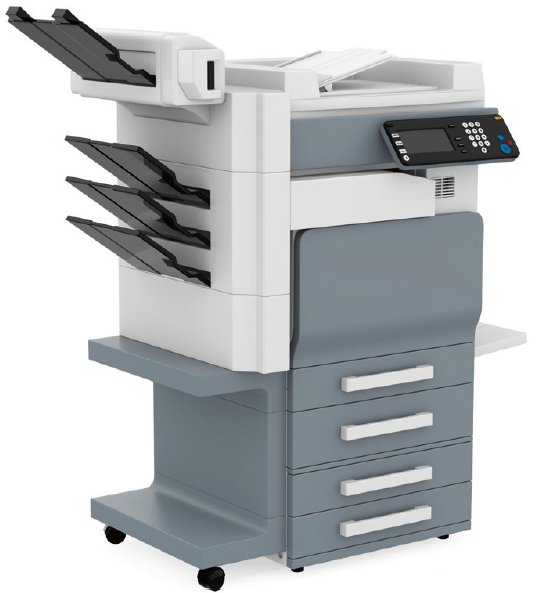
Against a backdrop of fossil fuel depletion and environmental concerns, the demand for renewable energy and energy conservation continues to grow. Multifunction peripherals (MFPs), which are typical products among office automation (OA) equipment, have become essential business equipment.
However, there is a need to reduce paper usage to help conserve forests, and reducing power consumption has also become a major challenge. One important point in cutting power consumption by MFPs is to reduce the power consumed in each mode, namely sleep, standby, and printing. In all modes, the power controller, which performs power conversion, plays a key role. In addition, each mode in an MFP also requires control technologies for minimizing power consumption.
2. Challenges
To measure the power consumption of MFPs in the sleep, standby, and printing modes, you need to select the appropriate current range for measuring currents, from micro currents to several amperes. Additionally, since there may be currents with high peak values relative to the RMS value, if the appropriate current range is not selected, a significant measurement range error for the current can occur.
Furthermore, setting the power range is also an important aspect of power measurement. The power range is determined by the set voltage range and current range, so selecting appropriate voltage and current ranges is a critical factor in reducing power measurement errors. Therefore, when selecting a power meter, you have to not only consider accuracy but also ensure that the instrument has sufficient current range available to allow for measurements from micro currents to currents at rated operation. This is essential for performing high-precision power measurement and verification on efficiently reducing power consumption.
3. Solutions Provided by the WT5000
- High-precision power measurement with ±0.03% accuracy
- High-precision measurement of small currents through direct-current input
- High-precision measurement of the power factor and other power parameters
- High-precision measurement of AC/DC and DC/DC conversion efficiency
- Measurement of integrated power and integrated current
- Harmonic/flicker measurement in accordance with IEC standards
4. Suggestions for using the WT5000
4.1 High-precision power measurement with ±0.03% accuracy
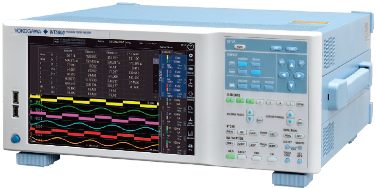
The WT5000 achieves a world-class total measurement accuracy of ±0.03% (50/60 Hz). When measuring currents with high peak values relative to the RMS value, range errors need to be reduced. With a power accuracy of ±(0.01% of reading + 0.02% of range) (50/60 Hz), the WT5000 features minimal range errors, allowing for high-precision power measurements. The power input is modular, so you can replace or expand it yourself. Three types of elements (30 A rated input, 5 A rated input, or dedicated current sensor input), give you the flexibility to carry out measurements across a wide range of current amplitudes with a single unit.
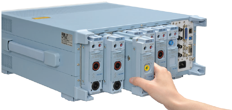
Figure 1. Changing an element in the WT5000
4.2 High-precision measurement of small currents through direct-current input
The 30 A high-precision element (760901) and 5 A highprecision element (760902) allow direct current input without the need for an external current sensor, enabling highprecision measurements in sleep, standby, and operation modes, respectively. The 5 A high-precision element (760902) offers the wide choice of 10 measurement ranges, namely 5 mA, 10 mA, 20 mA, 50 mA, 100 mA, 200 mA, 500 mA, 1 A, 2 A, and 5 A, so you can even select the appropriate range for measuring small currents in sleep or standby modes.
Because the power range is determined by the set voltage range × current range, choosing the appropriate voltage and current ranges is essential for reducing power measurement errors and achieving high-precision measurements.
Additionally, there are convenient range-changing features for when significant current fluctuation occurs during printing. These include the auto-range setting function (range up, range down), a feature for changing to the specified range when peak over-range occurs during measurement from standby to printing, and the valid measurement range selection function that enables you to choose the appropriate measurement range based on usage conditions.
4.3 High-precision measurement of the power factor and other power parameters
MFPs convert 50 Hz/60 Hz AC power from sources like electrical outlets into DC power internally to supply power.
Since the power value of AC power changes depending on the voltage, current, and phase difference, it is important to minimize the phase difference and suppress harmonics to bring the power factor as close to 1 as possible.
The WT5000 measures the power value through the PFC circuit and calculates the power factor. It can also simultaneously measure and display other parameters such as voltage, current, active power, apparent power, and reactive power, so changes in each parameter can be monitored simultaneously.
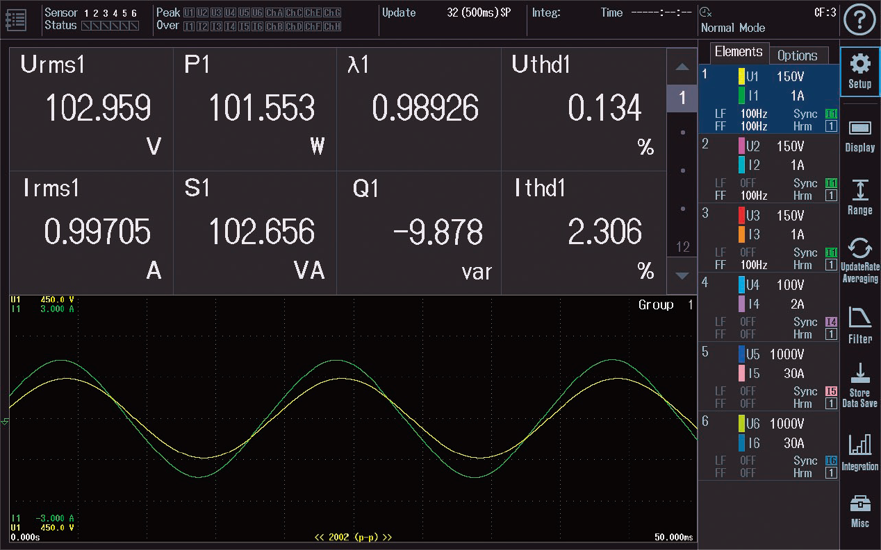
Figure 2. Display example of voltage, current, power factor, THC, etc.
4.4 High-precision measurements of AC/DC and DC/DC conversion efficiency
MFPs are equipped with several conversion circuits inside.
Because harmonic suppression is crucial when connecting to a standard commercial AC power supply, a PFC (Power Factor Correction) circuit is incorporated. Additionally, MFPs also have a built-in DC/DC converter, which controls the DC voltage level. Designing these circuits for minimal power loss is extremely important, and the WT5000, which features multi-channel input, enables you to measure the efficiency of each circuit with high-precision.
4.5 Measurements of integrated power and integrated current
The WT5000 comes equipped with an integration function that measures long-term power consumption (Wh) and current consumption (Ah).
The integration function includes the integration of active power (electrical energy), current (amount of current), apparent power (apparent electrical energy), and reactive power (reactive electrical energy).
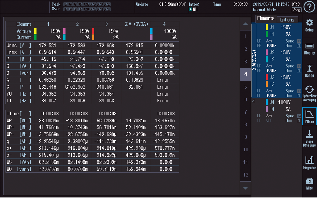
Figure 3. Example of the integrated power/integrate current measurement screen
4.6 Harmonic/Flicker measurement in accordance with IEC standards
Combined with the IEC Harmonic/Flicker measurement (/G7 option) and the IS8010 Integrated Software Platform, which is PC application software, the WT5000 can perform harmonics testing compliant with IEC61000-3-2 or voltage fluctuation/flicker testing compliant with IEC61000-3-3. In addition, using the special CT200 AC/DC current sensor model, it can also perform harmonic and voltage fluctuation/ flicker tests for currents exceeding 16 A per phase, in compliance with IEC61000-3-11 and IEC61000-3-12.
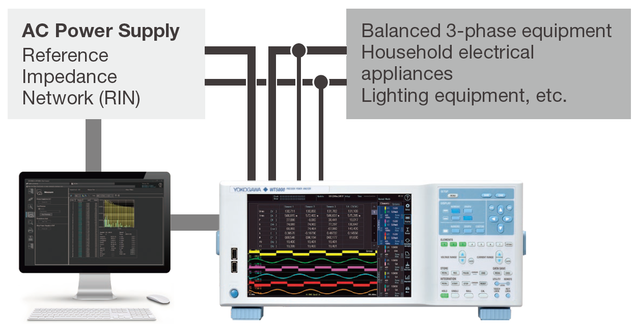
Figure 4. Harmonic/flicker test system compliant with the IEC standards
4.7 Utilization of highly reliable power data with guaranteed accuracy
Recent years have seen more and more waveform measuring instruments coming equipped with the capability to calculate power meter data. While being able to calculate power with a waveform measuring instrument is very convenient because it ensures contemporaneousness of data even in transient phenomena, there is an important point to note: the measurement accuracy of the power values must be traceable to national standards.
The main purpose of a waveform measuring instrument is to accurately capture the waveform of the measured signals with high bandwidth and high sampling rates using voltage and current probes. Therefore, the power calculation results obtained using a waveform measuring instrument lack measurement accuracy, unlike data measured by a power meter. Consequently, the reliability of such results must be carefully verified. Yokogawa power meters, on the other hand, establish and maintain high-precision measurement standards traceable to national standards, providing reliable data for parameters such as voltage, current, and active power.
The IS8000 Integrated Software Platform supports traceable* power measurements taken by the WT5000, as well as data transfer by the DL950 ScopeCorder at a maximum speed of 20 MS/s across eight channels. This enables display of highly reliable power meter data and waveform data on the same time axis.
* Power Traceability: Calibration technology supporting the performance of the WT5000 high-precision power meter
“Yokogawa’s power calibration technology to support high-precision power analysis”
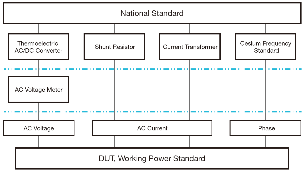
Figure 5. Traceability system diagram for the new power calibration system
4.8 Abnormality detection through continuous monitoring of power values and waveform data
When continuous measurement of voltage, current, and power data is required over an extended period, the IS8000 Integrated Software Platform allows for real-time monitoring and saving of power parameter trends. Additionally, the WT5000’s data streaming (/DS option) enables simultaneous monitoring and recording of both numerical power data and waveform data. With this feature, you can zoom in on areas with abnormalities in power measurements and analyze the corresponding waveform data with a single WT5000 unit.
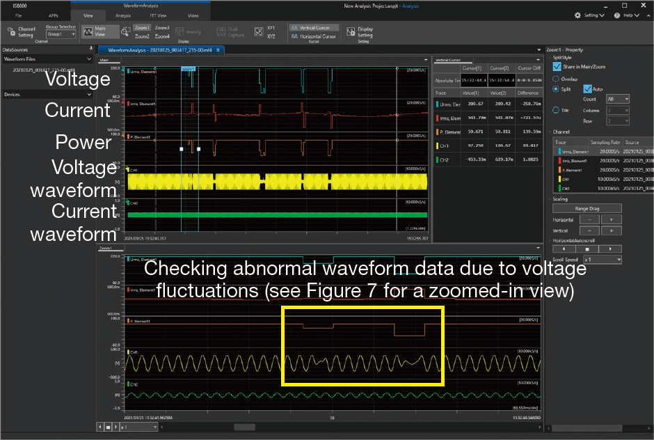
Figure 6. Voltage, current, and power trends displayed with the IS8000
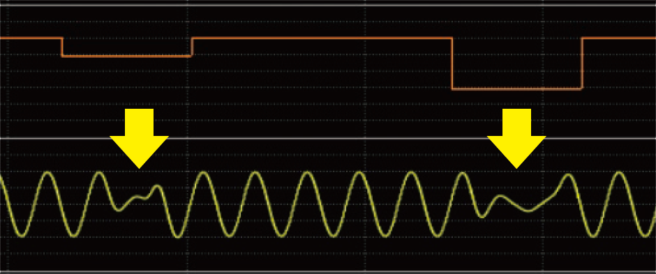
Figure 7. Zooming into areas of reduced power to inspect the waveform abnormalities
4.9 Other measuring instruments useful in MFP development
DL950: Long-term data recording and high-speed measurement at abnormal signal occurrences
The DL950 ScopeCorder, which is a multi-channel instrument for measuring isolated waveforms, has a dual-capture function that can capture waveforms at different sampling rates. Waveforms of sudden transient events can be captured at a high sampling rate while acquiring data at a low sampling rate to identify long-term trends. Additionally, the IS8000 Integrated Software Platform enables you to synchronize acquired waveform data and numerical power data from the WT5000 and display it using IEEE1588, allowing more detailed waveform observation during power fluctuations.
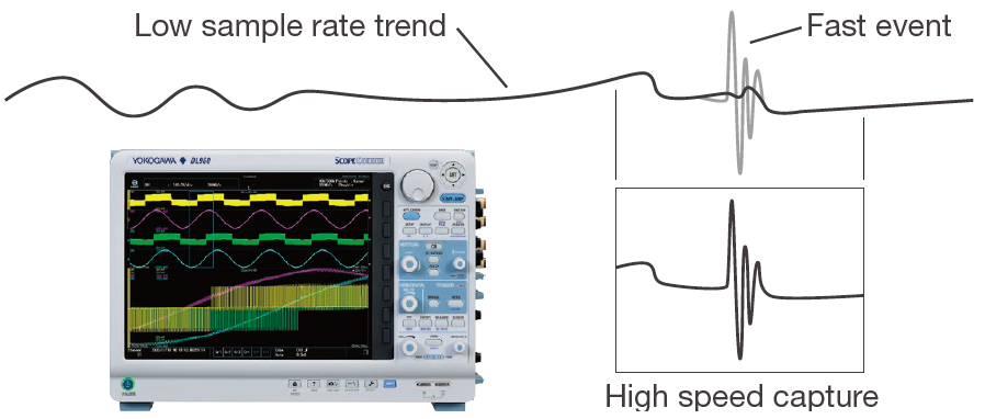
Figure 8. Example of measurement with the DL950’s dual-capture function
DLM3000HD/DLM5000HD: Observation of PFC circuit waveforms
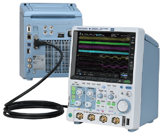
The DLM3000HD High-Definition Oscilloscope or DLM5000HD with eight channels, which have excellent waveform observation performance and operability, can be utilized to check the operation of a power supply and PFC circuit.
Indústrias Relacionadas
Produtos e Soluções Relacionadas

Power Analyzers and Power Meters
Industry-leading accuracy for efficiency, harmonics, and power parameters, ensuring regulatory compliance and confident design of energy-efficient systems.

WT5000 - Highest Precision
- Up to 7 wattmeters / Modular
- 0.01% of rdg + 0.02% of rng
- DC to 1MHz
- 4 motor inputs
- Harmonics to 500th order
- IEC 61000 compliance testing