720212 High-Speed Isolation Module

The Yokogawa 720212 Isolation Module sets a new benchmark by redefining the limits of high-speed, high-accuracy isolated measurement.
Combining 200 MS/s sampling with 14-bit resolution, it brings together speed and safety in ways that few digitizers can. Designed for engineers who need reliable, high-fidelity data in electrically demanding environments, this module represents the next evolution in precision isolation technology.
Key Features
- High-Speed Data Capture with Fine Detail: Sample at 200 MS/s to capture switching events, transients, and noise dynamics with exceptional clarity and 14-bit precision
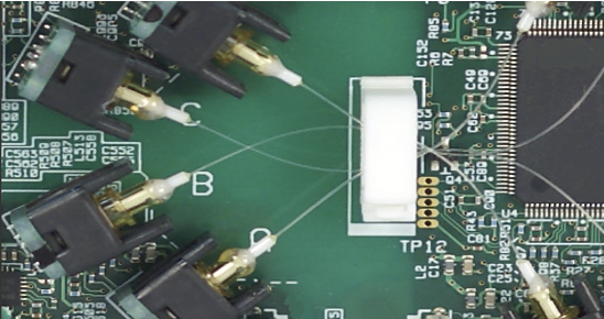 Optically Isolated Channels: Each input channel is optically isolated, providing robust protection against ground loops and common-mode interference while maintaining accurate differential measurements even in high-voltage systems.
Using high-speed optical fiber-based transmission, IsoPRO™ technology enables 1kV isolated measurements*. The module achieves high-speed ADC clock and data isolation.
 Optically Isolated Channels: Each input channel is optically isolated, providing robust protection against ground loops and common-mode interference while maintaining accurate differential measurements even in high-voltage systems.
- Exceptional Signal Integrity: The combination of high sampling rate, wide dynamic range, and low noise floor ensures that every captured waveform reflects true system behavior - critical for high-speed power and control analysis
- Seamless System Integration: Fully compatible with Yokogawa’s ScopeCorder (DL950) and High-Speed DAQ (SL2000) platforms, the 720212 extends system capability without adding setup complexity.
- Engineered for Modern Power and Energy Applications: Purpose-built for inverter testing, EV drivetrain development, and renewable-energy conversion systems, the 720212 delivers the precision and safety required to observe high-efficiency inverters operating with high voltages, large currents, and ever-increasing switching speeds
| Item | Specifications |
|---|---|
| Standard operating conditions | Temperature: 23 ±5 °C Humidity: 20 to 80 % RH After a 30 minute warm-up and after calibration |
| Effective measurement range | 20 div (display range: 10 div) |
| Number of input channels | 2 |
| Input coupling settings | AC, DC, GND |
| Maximum sample rate | 200 MS/s |
| Input type | Isolated unbalanced |
| Frequency characteristics1 (−3 dB point when a sine wave of amplitude ±3 div is applied) | DC to 40 MHz |
| Voltage scale setting | 10 mV/div to 20 V/div (1-2-5 steps) (when using 1:1 probe factor) |
| Maximum input voltage (at a frequency of 1 kHz or less) | |
| Combined with the 700929 (10:1), 702902 (10:1), or 701947 (100:1)2 | 1000 V (DC+ACpeak) CAT II |
| Combined with the 701901 + 701954 (1:1)4 | 200 V (DC+ACpeak) CAT II |
| Direct input (cable that does not comply with the safety standards)6 | 42 V (DC+ACpeak) |
| Maximum rated voltage to ground – between input and ground and between inputs (at a frequency of 1 kHz or less) | |
| Safety standard’s working voltage | |
| Combined with 700929 (10:1), 702902 (10:1), 701947 (100:1)3 or combined with 701901 + 701954 (1:1)5 | 1000 Vrms CAT II |
| Direct input (cable that does not comply with the safety standards)7 | 42 V (DC+ACpeak) |
| Vertical (voltage) axis accuracy DC accuracy1 | ±(0.5 % of 10 div) |
| Input connector | BNC connector (isolated type) |
| Input impedance | 1 MΩ ±1 %, approx. 35 pF |
| −3 dB point when AC coupled | 10 Hz or less |
| Common mode rejection ratio | 80 dB or more (50/60 Hz) (typical value8) |
| Residual noise level (input section shorted) | ±0.15 div (typical value8) |
| Withstand voltage | 5400 Vrms for 2 seconds (across each input terminal and earth), 60 Hz |
| Allowable transient surge voltage | ±2100 Vpeak (across each input terminal and earth) |
| Insulation resistance | 500 VDC, 10 MΩ or more (across each input terminal and earth) |
| A/D converter resolution | 14 bits (600 LSB/div) |
| Temperature coefficient | Zero point: ±(0.1 % of 10 div)/°C (typical value8) Gain: ±0.05%/°C (typical value8) |
| Bandwidth limit | Select Full (no bandwidth limit) or from the following filters. Analog filter Cutoff frequency: 5 MHz (typical value8) Cutoff characteristics: –12 dB/OCT (typical value8) Digital filter Cutoff frequency: 2.56 MHz, 1.28 MHz, 640 kHz, 320 kHz, 160 kHz, 80 kHz, 40 kHz, 20 kHz, 10 kHz Filter type: IIR |
| Probe attenuation settings | Voltage probe: 1:1, 2:1, 5:1, 10:1, 20:1, 50:1, 100:1, 200:1, 500:1, 1000:1, 2000:1, 5000:1, 10 k:1, 20 k:1, 50 k:1 Current probe: 0.1 A:1 V, 0.2 A:1 V, 0.5 A:1 V, 1 A:1 V, 2 A:1 V, 5 A:1 V, 10 A:1 V, 20 A:1 V, 50 A:1 V, 100 A:1 V, 200 A:1 V, 250 A:1 V, 400 A:1 V, 500 A:1 V, 1 kA:1 V, 2 kA:1 V, 5 kA:1 V, 10 kA:1 V, 20 kA:1 V, 50 kA:1 V |
| Wiring / measurement points |
|

1. Value measured under standard operating conditions.
8. Typical values represent typical or average values. They are not strictly warranted.

DL950 ScopeCorder
Capture and analyze a wide variety of electromechanical signals and serial buses. High sample rate, long recording times, advanced triggers, and real-time analysis.

Brochures
Drawings
Top

