Scale Optical Device Testing From R&D to Production
The Multi Application Test System (MATS) is an integrated platform for high-precision, high-throughput testing of optical devices, transceivers, and photonic components. Built with proven laboratory grade technology, it delivers stable, repeatable, and accurate measurements required in photonics R&D, new product introduction, and volume manufacturing.
Unlike other platforms, only Yokogawa offers a unified system with optical and SMU modules, hot-swappable reconfiguration, and proven long-term reliability in 24/7 high-volume production. For optical transceiver characterization, MATS is commonly paired with instruments such as OSAs, WLMs, BERTs, and high-speed oscilloscopes.
Generations of Proven Production Test
Yokogawa’s optical test platform builds on multiple generations of proven production systems. The latest-generation AQ2300 platform adds SMU modules to support LIV testing required for silicon photonics devices. Modules are platform-specific and are not interchangeable between mainframes.


- Easy-to-use touch panel
- 3 and 9-slot frame controllers
- Hot-swappable reconfiguration
- Synchronized trigger I/O by frame or module
- USB, Ethernet, GPIB (optional)

- 1310, 1550, 1625 or 1650 nm
- Output level: ≥10 dBm
- Level stability: ±0.005 dB or less

- 1310, 1550, 1625 or 1650 nm
- Output level: ≥10 dBm
- Level stability: ±0.005 dB or less


1-channel high power type with analog output
The high-performance optical power meter module designed to measure high optical input levels.

Si Optical Sensor Head with a large diameter detector
For short-wavelength use. Measurements can be performed directly at hand.
With the connector adapter removed, free-space light can also be measured.

- Detector type: InGaAs, φ5 mm
- Power range: −90 to +15 dBm (CW)
- Wavelength range: 800 to 1700 nm


- Single mode model
- Low insertion loss: 1.0 dB
- Reproducibility: ±0.01 dB

- Single mode model
- Low insertion loss: 1.0 dB
- Reproducibility: ±0.01 dB

- 2-Channel
- Ranges: ±6 V, ±600 mA
- Resolution: 100 µV / 1 pA
- Sweep: Linear, Log, Custom
- Output: DC, Pulse (50 µs to 1 s)

- Easy-to-view color display
- USB port for data storage
- Remote monitoring and measurement through a LAN

- Easy-to-view color display
- USB port for data storage
- Remote monitoring and measurement through a LAN

- 1310, 1550, 1625 or 1650 nm
- Output level: ≥10 dBm
- Level stability: ±0.005 dB or less

- C-band or L-band
- 1 MHz step fine tuning
- Output level: ≥12.5dBm


- Large diameter detector
- 800 to 1700 nm, -90 to +15 dBm
- 400 to 1100 nm, -90 to +10 dBm

- Single mode model:
- 1200 to 1700 nm
- 0 to 60 dB
- Multi mode model:
- 800 to 1370 nm
- 0 to 45 dB

- Built-in optical power meter
- Single mode model:
- 1200 to 1700 nm
- 0 to 60 dB
- Multi mode model:
- 800 to 1370 nm
- 0 to 45 dB

- 1x4 or 1x8 configuration
- Single mode or Multi mode
- Low insertion loss: 1.0 dB
- Reproducibility: ±0.01 dB

- 1x16 configuration
- Single mode or Multi mode
- Low insertion loss: 1.0 dB
- Reproducibility: ±0.01 dB

- Dual 1x2 or Dual 2x2 configuration
- Single mode or Multi mode
- Low insertion loss: 1.0 dB
- Reproducibility: ±0.01 dB

- Supports 10G XFP, SFP+, XENPAK
- Power supply and power current monitoring
- I2C/MDIO interface

Static characterization of laser diode (LD) and photodiode modules
The AQ2300 streamlines the test by synchronizing source measure unit (SMU) and optical power meter (OPM) measurements during sweep measurements in a single test platform. enabling electrical and optical parameters to be synchronously acquired in a single platform. This built-in inter-channel synchronization enables efficient I-L characterization without additional external synchronization wiring. For more comprehensive optical characterization, the measurement system can be integrated with the AQ6151B Optical Wavelength Meter and AQ6361/AQ6370E Optical Spectrum Analyzer to evaluate wavelength and spectrum alongside electrical and optical power characteristics.
[Measurement items] I-L measurement, DC extinction ratio, PD current, modulator current, wavelength, spectrum
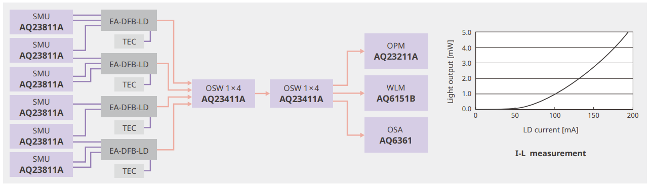
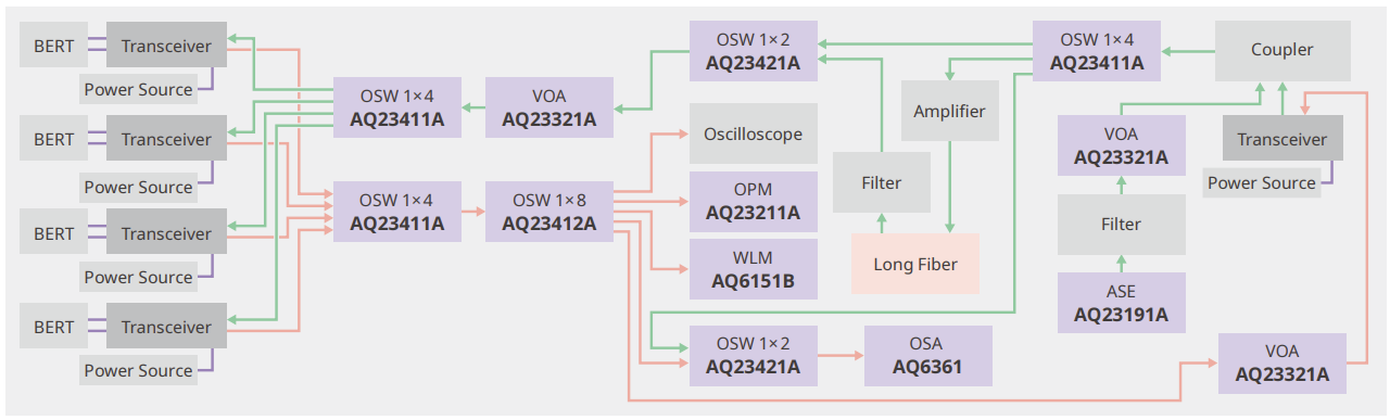
Optical transceiver measurements
The AQ2300 provides comprehensive optical transceiver evaluation by combining optical power measurement, optical attenuation, optical path switching, and ASE noise loading within a modular system. Multiple transceiver channels can be routed through optical switches, while variable optical attenuators enable controlled adjustment of optical signal levels. When combined with the AQ6151B Optical Wavelength Meter and the AQ6361/AQ6370E Optical Spectrum Analyzer, the system also delivers comprehensive wavelength and spectral analysis. The AQ23191A ASE Light Source can also be incorporated into the optical path to evaluate transceiver performance under controlled ASE noise-loading conditions.
[Measurement items] Optical power, wavelength, Spectrum, optical power adjustment, ASE noise loading
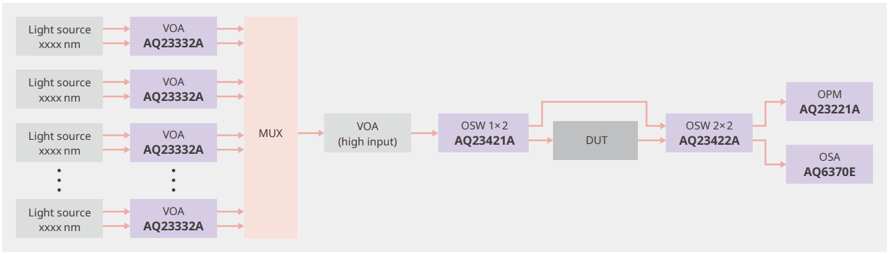
Optical Fiber Amplifier Measurements
The AQ2300 supports optical fiber amplifier evaluation under wavelength-division multiplexed (WDM) conditions. Multiple optical signals at different wavelengths can be independently controlled, attenuated, and multiplexed to create realistic inputs for the amplifier under test. Combined with the AQ6370E/AQ6361 Optical Spectrum Analyzer, the system can evaluate gain, gain flatness, noise figure, and ASE across multiple wavelength channels. The AQ6370E/AQ6361 provides dedicated optical amplifier analysis capabilities for gain and noise figure evaluation, while the AQ2300 enables flexible control of optical power levels and measurement paths for multi-wavelength testing.
[Measurement items] Gain, gain flatness, noise figure, ASE noise
Loss measurement of optical passive components
The AQ2300 supports measurement of optical loss measurements for passive components such as optical fibers, connectors, couplers, etc. By combining optical sources, power meters, attenuators and switching modules in single modular system, engineers can evaluate the optical insertion loss and crosstalk of various optical passive components.
[Measurement items] Optical insertion loss, crosstalk

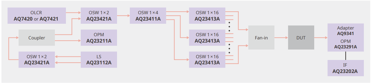
MPO component inspection system
The AQ2300 can be combined with the AQ7420 or AQ7421 High-Resolution Reflectometer to build a multi-fiber inspection system for MPO and multi-fiber optical components. Optical switches route the measurement path across multiple fibers, enabling insertion loss and optical return loss measurements in a multi-channel configuration. The AQ7420 and AQ7421 provide high-resolution reflection analysis to identify the position and magnitude of localized reflections, helping detect defects such as micro-cracks that may be difficult to identify through conventional loss measurements alone. By combining this detailed reflection analysis with the AQ2300's flexible optical switching and power measurement capabilities, the system supports comprehensive evaluation of insertion loss, total and partial optical return loss, and micro-cracks in MPO components.
[Measurement items] Insertion loss, total optical return loss, partial optical return loss, micro-crack detection
High-speed sweep testing of multi-power-supply optical devices
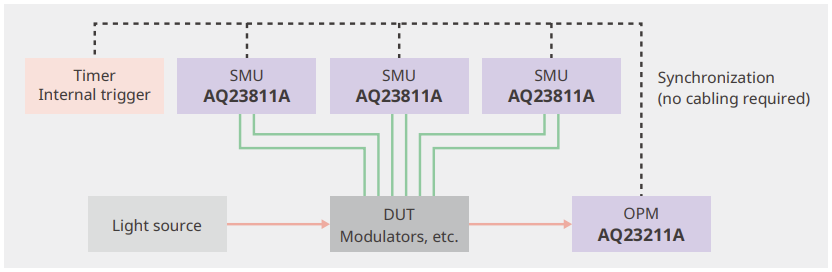
The AQ2300 enables high-speed synchronized sweep measurements for devices with multiple electrical signals. By taking advantage of the AQ2300’s internal trigger and inter-channel synchronization, the system simplifies sweep testing to evaluate optimal voltage and current conditions and characterize optical power variation across multiple electrical operating parameters.
[Measurement items] Searching for optimal voltage or current conditions, optical power variation

Overview of optical communications via optical fibers including: signal conversion, optical fiber benefits, techniques like wavelength division multiplexing (WDM) for increased capacity, key components like optical amplifiers and spectrum analyzers for maintaining transmission quality.


One possible way to create a non-blocking 4x4 switch on the AQ2200 Multi Application Test System is by using multiple 2x2 switch modules. Please refer to the attached file.
The analog output of the AQ2200-211 Sensor Module converts digital data to analog data in 100 us interval. It is not a direct output of an analog amplified but it is a D/A output.
The following are the specifications for the AQ2200-111 1490nm DFB Module:- Center wavelength: 1490nm+/-10nm- Wavelength accuracy: 0.05nm- SMSR: 30dB or morePlease refer to the datasheet for the AQ2200-111(1310) ...
Please download and refer to the attached document for complete instructions on how to upgrade the firmware for the AQ2201/AQ2202 Frame Controller.
The meaning of "Monitor port: -13 dB" is that -13 dB corresponds to about 5% (10Log(0.05) nearly equals to -13). That is, output power is divided by an optical coupler at a ratio of 95:5, and 5% is for monitor ...
Yes, the AQ2200-141/-142 FP-LD modules have a built-in isolator. The isolation is 35dB.
The Chopped Light mode is used: To increase measurement level sensitivity by cutting the high frequency noise To detect only the light that the LS emitted, effective for free space measurement. In free space ...
If you have products currently in China that require calibration or repair, you may either return them to your local Yokogawa service center or the Yokogawa China Service & Repair Center. Please be advised that ...
No, unfortunately due to the number of current fiber combinations, we do not stock optical fibers. There are many companies that specialize in optical fiber cords.
Product Overviews

From visible light to telecommunication bands and even up to applications in the 2000nm region, optical testing professionals count on the Yokogawa Test&Measurement optical testing family of products. For decades, these precision-based optical measuring instruments have met and exceeded the needs of many customers’ experimental requirements. Applicable to a range of uses in R&D, manufacturing, and academia, Yokogawa Test&Measurement OSAs, OTDRs, OWMs, modular manufacturing test systems, and more deliver quality, consistency, ease of use, and market leadership for all manner of optical test applications.
How-tos

This video demonstrates side mode suppression ratio (SMSR) analysis using an AQ6370E OSA and explains how to adjust the signal span to capture side modes and execute SMSR analysis to detect and locate the closest peaks from a 1310 nanometer laser via a connected light source module. SMSR analysis allows engineers to quickly identify and quantify the differences between the main peak and any side peaks in terms of nanometers and power which helps ensure the quality and accuracy of a laser's output. Manufacturers want to see a single, clean peak in a laser's output without side modes or additional peaks, to indicate a laser is performing as expected.

