Steady State vs. Transient Power Analysis
Comparing Measurement Approaches for Accurate Efficiency and Dynamic Power Analysis
Modern power electronic systems such as motor drives, renewable energy inverters, and switching power supplies must be evaluated under a variety of operating conditions. Some measurements are concerned with how a system performs once it has reached a stable operating point, while others focus on how the system behaves during rapid electrical events such as switching transitions or startup conditions.
These two perspectives lead to two different types of analysis: steady state power analysis and transient power analysis. Each provides different insights into the operation of an electrical system, and both are necessary to fully understand system performance.
Steady state analysis focuses on long term electrical performance and efficiency once the system is operating normally. Transient analysis focuses on short duration electrical behavior that occurs when signals change rapidly. Because these analyses examine different aspects of system behavior, they traditionally rely on different measurement techniques and instruments.
Steady State Power Analysis
What is Steady State Power Analysis?
Steady state power analysis evaluates a system once it has reached a stable operating condition. In this state, voltage and current waveforms repeat consistently from cycle to cycle and the electrical behavior of the system remains relatively constant over time.
The primary goal of steady state analysis is to measure power and energy with very high accuracy and fidelity. These measurements allow engineers to determine how efficiently a system converts electrical energy and how much power is being lost within the system.
Typical measurements include:
- RMS voltage
- RMS current
- Active power
- Reactive power
- Apparent power
- Power factor
- Energy consumption
- Harmonic distortion
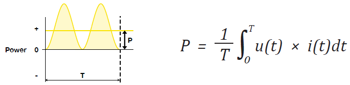
One of the most important functions of steady state analysis is accurately comparing input and output power in order to calculate system efficiency.
η = Pout / Pin
Because modern power electronic systems often achieve efficiencies greater than 95 percent, even small measurement errors can significantly affect calculated efficiency. For this reason steady state power analysis prioritizes high measurement accuracy, stable calibration, and precise phase measurement between voltage and current.
Steady state analysis also relies on averaging measurements across multiple cycles of the waveform. By observing repeated waveform periods and averaging the calculated values, noise and short term variations can be reduced, allowing accurate determination of long term system performance.
This approach is commonly used when evaluating the efficiency of switching power supplies, measuring the power consumption of appliances, testing motor drive efficiency, or verifying the performance of grid connected inverters.
Typical Uses of Steady State Analysis
Steady state analysis is commonly used when engineers need to understand the overall electrical performance of a system operating under normal conditions.
Examples include measuring the efficiency of a switching power supply, evaluating the power consumption of an appliance, testing the electrical efficiency of a motor drive, or verifying the performance of a solar inverter delivering power to the grid. In each of these cases the system is operating in a relatively stable condition and the primary interest is in accurate measurement of power flow and energy conversion.
Transient Power Analysis
What is Transient Power Analysis?
Transient power analysis focuses on electrical behavior during short duration events when voltage and current change rapidly. These events occur during switching transitions, startup sequences, load changes, or other dynamic operating conditions.
Instead of focusing on long term averages, transient analysis examines how voltage and current waveforms behave during specific electrical events.
Typical transient observations include:
- switching transitions
- voltage overshoot and ringing
- current spikes
- timing relationships between signals
- dynamic waveform behavior during system events
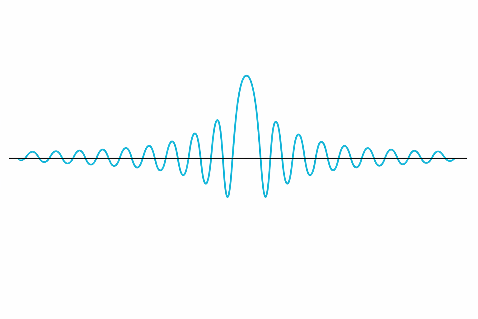
In transient analysis, the goal is often to understand how a specific event influences system behavior. Because these events may occur over only a small portion of the waveform, it can be useful to adjust the calculation window or analysis period so that measurements correspond directly to the event being studied.
For example, an engineer investigating switching losses in a DC-DC converter may adjust the analysis window to align with the switching transition of a power device. In this case the calculated RMS values, instantaneous power, or energy measurements are evaluated only over the portion of the waveform where the event occurs.
This ability to analyze measurements within a selected time window allows engineers to study dynamic behavior that would be hidden in long term averaged measurements.
Typical Uses of Transient Analysis
Transient analysis is commonly used when engineers are developing or debugging power electronic circuits. Engineers may examine switching waveforms in a DC-DC converter, observe PWM signals in a motor inverter, or investigate voltage spikes that occur during device switching.
In these cases, the most important capability is the ability to clearly see waveform behavior over time. Measurement accuracy is still important, but the priority is typically bandwidth and resolution so that rapid electrical events can be observed.
Traditional Measurement Approaches
Because steady state and transient analyses place different demands on measurement systems, they have traditionally been performed using different types of instruments.
Steady state power analysis has long relied on precision power analyzers as the primary measurement tool. These instruments are specifically designed to deliver highly accurate voltage and current measurements with precise phase alignment, enabling reliable calculation of real power, reactive power, efficiency, and harmonic content. Their architecture is optimized for stable, high fidelity measurements over multiple waveform cycles, using averaging techniques to reduce noise and improve repeatability. For this reason, power analyzers have been the standard for validating efficiency and power quality under steady operating conditions.
Transient analysis, in contrast, has traditionally been performed using oscilloscopes. Oscilloscopes provide the bandwidth and sampling speed required to capture fast changing signals, making them well suited for observing switching behavior, timing relationships, and other dynamic waveform characteristics. This makes them essential for understanding how systems behave during switching events, startup conditions, and load changes.
However, accuracy becomes a significant challenge when oscilloscopes are used to validate dynamic power behavior. Accurate power measurement depends on precise amplitude accuracy, tight phase alignment between voltage and current, and well characterized measurement uncertainty. These requirements become even more critical during fast transient events where small timing or amplitude errors can lead to large inaccuracies in calculated power. Since oscilloscopes are primarily optimized for waveform visibility and time resolution rather than metrology level accuracy, their use for quantitative power validation in dynamic systems has historically been limited.
As a result, each instrument has traditionally addressed a different aspect of power electronics measurement. Power analyzers provide high confidence in steady state power measurements, while oscilloscopes provide detailed visibility into transient electrical behavior, with inherent limitations when used for accurate power analysis.
A Better Way for Dynamic Analysis
As power electronics systems become faster and more efficient, engineers increasingly need to understand how transient electrical events influence overall power performance. Traditional workflows often require separate instruments for steady state power analysis and transient waveform observation, making correlation more difficult.
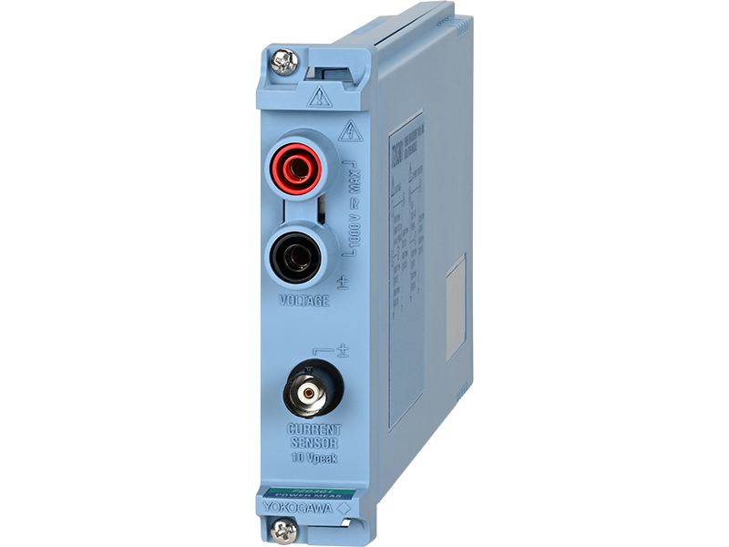
Yokogawa is addressing this need with the new 720301 Power Measurement Isolation Module for the ScopeCorder platform. The module enables transient voltage and current capture while also supporting power related calculations with a specified accuracy. It combines 16-bit resolution, 1 MS/s sampling, 300 kHz bandwidth, and basic accuracy approximately ±0.14%. With one voltage input and one current sensor input, it allows synchronized acquisition of the signals needed for RMS and power analysis.
Integrated with platforms such as the DL950 and SL2000, the module gives engineers a way to examine transient behavior while maintaining confidence in the underlying measured values.
Conclusion
Steady state and transient analyses provide complementary insight into modern power electronic systems. Steady state measurements quantify efficiency, power flow, and harmonic performance under stable conditions, while transient analysis reveals dynamic behavior during switching and other fast events.
These two perspectives have traditionally required separate instruments. Precision power analyzers are used for accurate, averaged power measurements, while oscilloscopes are used to capture high speed waveform behavior. As a result, engineers have typically relied on both tools to fully evaluate system performance.
The Yokogawa 720301 high resolution isolation module for the ScopeCorder platform addresses this gap by enabling transient waveform capture with defined measurement accuracy. This allows engineers to perform power related analysis and dynamic waveform observation within a single system, reducing measurement complexity while improving correlation between electrical behavior and power performance.
Related Products & Solutions

Isolated Oscilloscopes | ScopeCorders
- An integrated measurement system for every electromechanical application
- Modular platform combines oscilloscope and DAQ functionality
- Capture high-speed transients and low-speed trends

Power measurement 1 MS/s 16-Bit Isolation Module
- 2-Channel (1 Voltage and 1 Current Sensor)
- 1 MS/sec, 16-Bit
- 300 kHz Bandwidth
- Max. Input Voltage (DC + ACpeak): 1000V (Voltage) / 10V (Current)
- Accuracy Guaranteed Range: DC, 0.1 Hz to 100 kHz
*To perform calculations for RMS values or power values with guaranteed accuracy, the /G05 or /MT1 option is required.