701271 DSUB Strain Module

The Yokogawa 701271 is a two-channel D-Sub strain module designed for strain gauge and bridge-based measurements on the ScopeCorder high-speed DAQ platform. Used with compatible D-Sub strain heads such as the 701957 or 701958, it supports selectable bridge excitation, built-in shunt calibration, and 100 kS per second, 16-bit acquisition for capturing both static and dynamic strain behavior.
Key Features
- Two-Channel Strain and Bridge Measurement: Provides two isolated input channels designed for use with D-Sub strain bridge heads such as the 701957 and 701958, enabling accurate measurement of mechanical stress and deformation from strain gauge sensors.
- Built-In Shunt Calibration: Includes internal shunt calibration using the 1-gauge method, allowing quick verification of measurement accuracy without external calibration hardware.
- Flexible Bridge Configuration: Supports DC bridge inputs with selectable bridge voltages of 2 V, 5 V, or 10 V and gauge resistance ranges from 120 Ω to 1000 Ω, accommodating a wide range of strain gauges and transducers.
- Wide Measurement Range and Bandwidth: Covers strain ranges from ±500 µSTR up to ±20000 µSTR and supports mV/V input ranges from ±0.25 mV/V to ±10 mV/V, with frequency response from DC to 20 kHz for static and dynamic strain testing.
| Item | Specifications | ||||||||||||||||||||||||||||
|---|---|---|---|---|---|---|---|---|---|---|---|---|---|---|---|---|---|---|---|---|---|---|---|---|---|---|---|---|---|
| Standard operating conditions | Temperature: 23 ±5 °C Humidity: 20 to 80 % RH After a 30 minute warm-up and after calibration and auto balance |
||||||||||||||||||||||||||||
| Effective measurement range | −FS to +FS (set using upper and lower limits) | ||||||||||||||||||||||||||||
| Number of input channels | 2 | ||||||||||||||||||||||||||||
| Maximum sample rate | 100 kS/s | ||||||||||||||||||||||||||||
| Input type | DC bridge (auto balancing), balanced differential input, and isolated | ||||||||||||||||||||||||||||
| Auto balance type | Electronic auto balance | ||||||||||||||||||||||||||||
| Auto balance range | ±10000 µSTR (1 gauge method) | ||||||||||||||||||||||||||||
| Bridge voltage | Select from 2 V, 5 V, 10 V | ||||||||||||||||||||||||||||
| Gauge resistance | 120 Ω to 1000 Ω (bridge voltage: 2 V) | ||||||||||||||||||||||||||||
| Gauge factor | 1.90 to 2.20 (set in 0.01 steps) | ||||||||||||||||||||||||||||
| Frequency characteristics1 (−3 dB point when a sine wave of amplitude ±3 div is applied) | DC to 20 kHz | ||||||||||||||||||||||||||||
| mV/V range support | Supports the strain gauge transducer unit system. mV/V range = 0.5×(µSTR range/1000) |
||||||||||||||||||||||||||||
| Measurement range (FS) and measurement range | When using STR range
|
||||||||||||||||||||||||||||
| DC accuracy1 | ±(0.5 % of FS + 5 µSTR) | ||||||||||||||||||||||||||||
| Maximum input voltage (at a frequency of 1 kHz or less) | Between Input+ and Input−: 10 V (DC+ACpeak) | ||||||||||||||||||||||||||||
| Maximum rated voltage to ground – between input and case and between inputs (at a frequency of 1 kHz or less) | Between each terminal and earth ground: 42 V (DC+ACpeak) (CAT II, 30 Vrms) | ||||||||||||||||||||||||||||
| Input connector | 9-pin D-Sub connector (female) | ||||||||||||||||||||||||||||
| Common mode rejection ratio | 80 dB (50 Hz/60 Hz) or more (typical value2) | ||||||||||||||||||||||||||||
| A/D converter resolution | 16 bit (4800 LSB/div ±FS: Upper = +FS, Lower = −FS) | ||||||||||||||||||||||||||||
| Temperature coefficient | Zero point: ±5 µSTR/°C (typical value2) Gain: ±0.02%/°C (typical value2) |
||||||||||||||||||||||||||||
| Bandwidth limit | Select from Full, 1 kHz, 100 Hz, 10 Hz Cutoff characteristics: –12 dB/OCT (typical value2) |
||||||||||||||||||||||||||||
| Function | mV/V support. Supports the strain gauge transducer unit system. Shunt calibration support. Built-in shunt calibration relay (1 gauge method). |
||||||||||||||||||||||||||||
| Standard accessories | Connector shell set for soldering A1520JD (9-pin D-Sub): 2 pieces, A1618JD (connector shell): 2 pieces |
||||||||||||||||||||||||||||
| Compatible accessories (sold separately) | Recommended bridge head 701957 (D-Sub 120 Ω, shunt-Cal, enhanced shield version, comes with a 5-m cable) Recommended bridge head 701958 (D-Sub 350 Ω, shunt-Cal, enhanced shield version, comes with a 5-m cable) |
||||||||||||||||||||||||||||
| Notes |
|
||||||||||||||||||||||||||||
| Module front view |
|

1. Value measured under standard operating conditions.
2. Typical values represent typical or average values. They are not strictly warranted.

DL950 ScopeCorder
Capture and analyze a wide variety of electromechanical signals and serial buses. High sample rate, long recording times, advanced triggers, and real-time analysis.

DL350 Portable ScopeCorder
A compact, battery-powered, touch screen instrument you can take into the field featuring the measurement and recording capabilities you need for maintenance and troubleshooting.
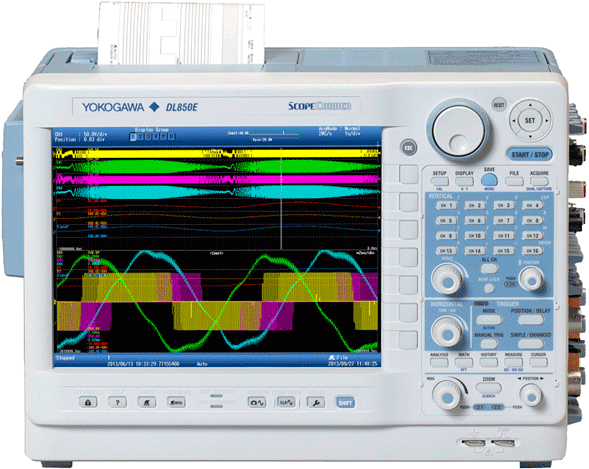
DL850E/DL850EV ScopeCorder
An all-in-one electromechanical measurement system offering the deepest measurement and analysis features to turn data into insights.

DL850/DL850V ScopeCorder
Combining the capabilities of an Oscilloscope and the characteristics of a Data Acquisition Recorder, the Yokogawa Scopecorder is a versatile tool for engineers making measurements in the industrial, transportation and energy sectors.

SL1000 High-Speed Data Acquisition Unit
Predecessor to SL2000. A PC-based ScopeCorder system capable of synchronizing multiple chassis.

