GM10 Modular Data Acquisition System


Precision. Flexibility. Intelligence.
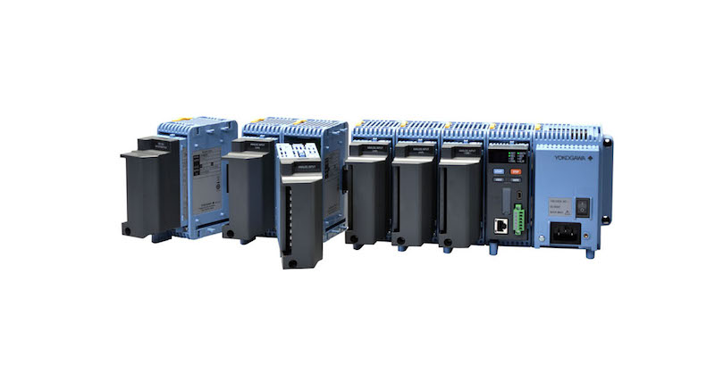
Designed for today’s rigorous test and measurement applications, the SMARTDAC+ GM Data Acquisition System delivers a robust, scalable, and easy-to-use solution for capturing, analyzing, and visualizing measurement data. Built on decades of Yokogawa’s innovative measurement technology, the GM system excels from laboratory testing to industrial field applications.
The SMARTDAC+ GM combines advanced measurement accuracy with a smart, modular design. With its “plug-and-lock” architecture, this system allows you to expand up to 420 channels per system, while simplifying installation and maintenance.
Applications
- Device Verification & Characterization: Test and validate the performance of industrial devices, appliances, and consumer electronics. Capture long-term trends (e.g., pressure, vibration, temperature) to verify product lifecycle performance.
- Field Testing & Remote Measurements: Use mobile connectivity and remote configuration for on-site or remote testing without sacrificing accuracy.
- Compliance & Quality Assurance: Achieve regulatory compliance (e.g. UL/CSA) with secure and reliable data logging.
Key Features
High Performance & Reliability
- Precision Data Acquisition: Benefit from high-accuracy measurements and secure data storage that support critical testing and quality assurance activities.
- Noise Tolerance: Engineered for electrically noisy environments, the system’s design minimizes interference to deliver consistent, reliable performance.
- Rapid Sampling & Dual Interval Measurement: Configure scan intervals from 1 ms to slower rates for long-term monitoring—capturing both transient and steady-state phenomena.
Modular Scalability & Flexibility
- Expandable: Scale your system from a single unit with up to 100 channels (or up to 420 channels in multi-unit configurations) to meet your test requirements.
- Plug-and-Lock Modules: Quickly add or remove I/O modules, reducing wiring complexity and maintenance downtime.
Intelligent Connectivity & Remote Access
- Web-Based Configuration & Monitoring: Set up and monitor your system in real time from any web browser, with live data viewing that lets you track trends, record test data, and perform on-the-fly adjustments.
- Open Network Integration: Communicate seamlessly using protocols such as Modbus, EtherNet/IP, SLMP, OPC-UA, and PROFINET, ensuring smooth integration with existing test setups and automation platforms.
Smart Functionality for Test & Measurement
- Advanced Math & Event Actions: Automate calculations—such as square roots, logarithms, and trigonometric functions—directly in the system. Schedule events like recording triggers and alarms to capture critical moments in your testing process.
- Predictive Detection & Health Monitoring: Leverage historical test data to build predictive models that detect subtle deviations or quality issues before they escalate.
Key Specifications
| Parameter | Specification |
|---|---|
| Scan Interval | Configurable from 1 ms (high-speed measurement) up to 5 s |
| Connectivity | Ethernet (10/100Base-TX), Bluetooth, USB, RS-422/485 |
| Communication Protocols | Supports Modbus, EtherNet/IP, OPC-UA, PROFINET, SLMP |
| Mounting Options | Desktop, DIN rail, and Wall-mounted installations |
| Operating Temperature | -20°C to 60°C |
| Expansion Capability | Supports up to 10 linked I/O modules per unit; scalable to 420 channels per system |
| Model | Name | Measurement/Application | Channels |
|---|---|---|---|
| GX90XA-10-U2 | Analog Input Module | DC voltage, thermocouple, RTD, contact (solid state relay scanner type) | 10 |
| GX90XA-10-L1 | DC voltage, thermocouple, contact (low withstand voltage solid state relay scanner) | 10 | |
| GX90XA-10-T1 | DC voltage, thermocouple, contact (electromagnetic relay scanner type) | 10 | |
| GX90XA-10-C1 | DC current (mA) (solid state relay scanner type) | 10 | |
| GX90XA-10-V1 | DC voltage, contact (solid state relay), high withstand voltage (600V/1000V insulation) | 10 | |
| GX90XA-04-H0 | DC voltage, thermocouple, RTD, contact (individual A/D type) | 4 | |
| GX90XA-06-R1 | 4-wire RTD, 4-wire resistance (solid state relay scanner type) | 6 | |
| GX90YA | Analog Output Module | Current output (isolated between channels) | 4 |
| GX90XD | Digital Input Module | Remote control input or operation recording | 16 |
| GX90YD | Digital Output Module | Alarm output | 6 |
| GX90WD | Digital I/O Module | Remote control input or alarm output | DI:8 / DO:6 |
| GX90XP | Pulse Input Module | Pulse signal data acquisition, integral count | 10 |
| GX90UT | PID Control Module | PID control (2 loops) | AI:2 / AO:2 / DI:8 / DO:8 |
| GX90EX | Expansion Module | Connects additional modules to the main unit | — |
GM10 Data Acquisition Module
| Type | GM10 | |
|---|---|---|
| No. of I/O channels | GM10-1: 100 max. | |
| GM10-2: 500 max. (or 420 with AI only) | ||
| Scan interval | 100/200/500 ms/1/2/5 s * Some intervals not available depending on system configuration and modules. |
|
| Internal memory (flash memory) |
GM10-1: 500 MB | |
| GM10-2: 1.2 GB | ||
| External storage media | SD memory card (SD/SDHC), up to 32 GB (1 GB incl.) Format: FAT32 or FAT16 |
|
| Data types | Event, display, alarm summary, manual sample, settings, and report (optional code /MT) | |
| Data format | Binary or text | |
| Alarms | Number: Max. 4 alarms per measurement channel Types: high limit, low limit, difference high limit, difference low limit, rate of change increase, rate of change decrease, delay high, delay low |
|
| Event actions | Specified actions can be performed when certain events occur. Number: 50 Events: alarms, remote control input, etc.; Actions: record stop/start, alarm ACK, etc. Timers: 12 Match time timers: 12 |
|
| Batch function | Manage data by batch name. Enter text fields and batch comments in data files. | |
| Calibration correction mode | Off, linearizer approximation, linearizer bias | |
| Security functions | Key lock and login functions. | |
| Insulation resistance | Between RS-422/485/Ethernet terminals and internal circuitry: 20 MΩ or greater (at 500 VDC) | |
| Ethernet | Electrical/mechanical specifications | IEEE 802.3 compliant (Ethernet frame type: DIX specification) |
| Implemented protocols | TCP, UDP, IP, ICMP, ARP, DHCP, HTTP, FTP, SMTP, SNTP, Modbus, dedicated protocol, SSL, DARWIN-compatible communication | |
| USB communication | Standards conformity | USB 2.0 compliant (recognized as a serial port by the PC) |
| Connector format/no. of ports | mini B/1 | |
| Implemented protocol | Dedicated protocol | |
| RS-422/485 (optional code /C3) |
Media | EIA RS-422/485 compliant |
| Implemented protocol | Dedicated protocol, Modbus/RTU, or DARWIN compatible communication | |
| Bluetooth (optional code /C8) |
Standards conformity | Bluetooth® Ver 2.1+EDR compliant |
| Supported profiles | SPP (serial port profile) | |
| Communication range | Approx. 10 m (depending on operating environment) (Class2) | |
| Implemented protocol | Dedicated protocol | |
| Ethernet/IP communications (optional code /E1) |
Can join Ethernet/IP networks as an adapter (server). | |
| Max. connections | 20 (or 10 max. at TCP/IP level) | |
| Supported protocols | EIP/PCCC, EIP/native | |
| Messaging | Explict (UCMM Class 3) +I/O (Class 1) | |
| Objects | Assembly, PCCC, Data Table | |
| WT communication (optional code /E2) |
Models supported | WT1800, WT500, WT300 |
| Supported communication | Ethernet | |
| Max. connected units | 16 | |
| Communication interval | 500 ms/1 s/2 s/5 s/10 s/20 s/30 s | |
| Acquirable data types | Voltage, current, power, power factor, phase, watt hours, harmonics, and others. | |
| Max. data assignments | 300 | |
| OPC-UA Server (optional code /E3) |
Communication | Type: OPC-UA Server |
| Encoding: UA Binary | ||
| Protocol: OPC UA TCP | ||
| Maximum number of connections: 3 sessions | ||
| Profile: Micro Embedded Device Server | ||
| Data acquisition | Measurement channel, computation channel, communication channel value and alarm status | |
| Data writing | Measurement channel (DO channel only), communication channel | |
| Port number | 4840 (changeable: 1 to 65535) | |
| Number of items | 300 max. (MonitoredItem/Session) | |
| Fastest period | 100 ms | |
| SLMP Communication (Mitsubishi PLC) (optional code /E4) |
Number of connection destination servers | 16 max. |
| Read cycle | 100 ms, 200 ms, 500 ms, 1 s, 2 s, 5 s, 10 s, 20 s, 30 s, 1 min | |
| Communicable internal data | Special relay (SM), special register (SD), input (X), output (Y), internal relay(M), latch relay (L), annunciator (F), edge relay (V), link relay (B), data register(D), link register (W), timer contact (TS), timer coil (TC), current timer value (TN), integration timer contact (SS), integration timer coil (SC), current integration timer value (SN), counter contact (CS), counter coil (CC), current counter value (CN), special link relay (SB), special link register (SW), direct access input (DX), direct access output (DY), index register (Z), file register (R, ZR), extended data register (D), extended link register (W) Device code is indicated in parentheses. |
|
| MATH (with Report function, optional code /MT) |
No. of MATH channels | GM10-1: 100 |
| GM10-2: 200 | ||
| MATH types | Basic math, statistics, special operators, conditional statements, and others. | |
| Communication channels (optional code /MC) |
No. of communication channels | GM10-1: 300 (C001-C300) |
| GM10-2: 500 (C001-C500) | ||
| Log scale (optional code /LG) |
Input types | LOG input, pseudo log (input that supports pseudo log), LOG linear (linear input within the log decade) |
| Scalable range | LOG input: 1.00E-15 to 1.00E+15 (max. 15 decades), [scale low limit] Pseudo log input/LOG linear: 1.00E-15 to 1.00E+15 (max. 15 decades), the mantissa of the scale low and high limits are assumed to be the same. |
|
| Multi-batch Function (optional code /BT) |
Number of multi batches | GM10-1: 6 max. |
| GM10-2: 12 max. | ||
| Aerospace Heat Treatment (optional code /AH) | Number of manageable schedules | GM10-1: 6 max. |
| GM10-2: 12 max. | ||
| Calibration correction mode | Off, linearizer approximation, linearizer bias, correction coefficient | |
| Number of set points | 2 to 12 | |
GM90PS Power Supply Module
| Type | GM90PS |
|---|---|
| Rated supply voltage | 100-240 VAC, 12-28 VDC (GM90PS-1N2W0) |
| Operating supply voltage | 90-132 VAC, 180-264 VAC, 10-32 VDC (GM90PS-1N2W0) |
| Power frequency (AC power supply) |
50 Hz±2%, 60 Hz±2% |
| Insulation resistance | Between power terminal and earth: 20 MΩ or more (at 500 VDC) |
| Withstand voltage | Between power terminal and earth: 3000 VAC (50/60 Hz), 1 minute 1000 VAC (50/60 Hz) for 1 minute (GM90PS-1N2W0) |
SMARTDAC+ GM common specifications
Standards supported
| CSA | CSA22.2 No.61010-1, installation category II, pollution degree 2 CSA 22.2 No.61010-2-030-12 |
|---|---|
| UL | UL61010-1, UL61010-2-030 (CSA NRTL/C) |
| CE |
|
| EMC Regulatory Arrangement in Australia and New Zealand (RCM) | EN55011 Class A Group 1 |
| Wireless communication standards of Australia and New Zealand (RCM) (optional code /C8) | AS/NZS4268, AS/NZS2772.2 |
| KC marking | Electromagnetic wave interference prevention standard, electromagnetic wave protection standard compliance |
| Environmental performance | WEEE directive support |
| Wireless (Bluetooth) | Supports radio wave regulations of Japan, America, Canada, Europe (EU), Australia, New Zealand, China, and Korea. |
Normal operating conditions
| Ambient temperature | -20 to 60°C If less, -20 to 50°C – When using the GX90YD, GX90WD, and GX90XA-T1 (electromagnetic relay type) – With the GM10/C8 (Bluetooth option) |
|---|---|
| Ambient humidity | 20 to 85% RH (no condensation) |
| Vibration | 5 ≤ f 8.4 ≤ f ≤ 160 Hz acceleration 9.8 m/s² (or less) |
| Shock | When ON, 98 m/s² or less, 11 ms, 3 times in 6 directions (±X, ±Y, ±Z) (excluding GX90YD and GX90WD) When OFF, 500 m/s² or less, approx. 10 ms, 3 times in 6 directions (±X, ±Y, ±Z) |
| Magnetic field | 400 A/m or less (DC and 50/60 Hz) |

VZ20X Analog Sensing Unit
The VZ20X enables data from a variety of isolated inputs to be measured at once and eliminates the need for numerous data measurement devices.

Brochures
Instruction Manuals
- Data Acquisition System GM First Step Guide (9.4 MB)
- Data Acquisition System GM User’s Manual (13.3 MB)
- Communication Command User’s Manual (4.4 MB)
Specifications
- GM10 Modular Data Acquisition System Specifications (3.6 MB)
- GX90XA/GX90XD GX90YD/GX90WD I/O Modules (3.0 MB)
- GM10 Data Acquisition Module GM90MB Module Base GM90PS Power Supply Module (2.6 MB)
- GX60 I/O Base Unit (Expandable I/O) GX90EX Expansion Module (2.8 MB)
Software
How-tos

Learn how to log power measurement data continuously from a digital power analyzer when connecting it to a data recorder to easily and securely collect and synchronize voltage, current, harmonics, and power data for long periods of time, while also collecting thermocouple, RTD, and standard analog signal, all in one place.

In this video, an Application Engineer shows users how to bring in Modbus/TCP-communicating instruments for measurement data synchronization across devices with the IS8000 Integrated Test and Measurement Software Platform from Yokogawa Test&Measurement.