DLM3000HD Series High-Definition Oscilloscope


Ideal for Everyday Use by Engineers
Adaptability is key in the development of high-performance and intelligent power semiconductor technologies and mechatronics in modern electric vehicles, motor controls, and energy-efficient electronic designs. With up to 16-bit high resolution, best-in-class startup speed, and high noise immunity, this four-channel oscilloscope provides an extensive set of analysis features in a compact design.
Setting a New Standard for High Definition
- 4 analog channels, 8-bit logic
- Bandwidth: 350 or 500 MHz
- Sample Rate: up to 2.5 GS/s
- Vertical resolution: 12-bit
- High resolution mode: up to 16-bit
- Measurement memory: up to 1 GigaPoints
- History waveforms: up to 200,000 triggers
- Simultaneous Multi-Channel Measurements: Up to 16-bit logic + 6 channels
- Up to 8 channels with two connected DLM3000HDs via DLMsync
- IEEE1588 Synchronous Support
- Highly-Responsive, Intuitive 8.4 in. Touchscreen
- with Traditional Oscilloscope Control Panel
- Superior Noise Immunity
- Logic and Serial Bus Analysis
- Additional Math Channels
- Extensive Voltage Ranges
- Compact, Light, Portable
Key Specifications
12- to 16-Bit High Resolution
Compared to traditional 8-bit oscilloscopes, the DLM3000HD measures 12-bit vertical resolution all the time. With its high-definition, resolution improves up to 16-bit, providing 16x more detail than existing high-definition oscilloscopes. Its high-resolution mode enables detailed measurement of events such as ringing and overshoot with impressive accuracy.

Multi-Channel Measurement Up to Eight Channels
A single DLM3000HD measures up to four channels simultaneously, while connecting two instruments extends synchronous measurement up to eight channels to enable evaluations via a single test.
Wide Bandwidth Measurement
Momentary phenomena such as overshoot at the rise of a high-speed inverter cannot be verified with low bandwidth oscilloscopes. The DLM3000HD combines a wide bandwidth of up to 500 MHz with a sample rate up to 2.5 GS/s.
Up to 2.5 GS/s (Four Channels at Once), Up to 1 G Points Memory
The DLM3000HD has a memory that can capture up to 1 G points (odd channels only) in a single waveform and up to 125 M points in a repetitive waveform acquisition to enable long-time measurement without reducing the sample rate.

Intuitive and Highly-Responsive Touchscreen
The 8.4 in. intuitive and highly-responsive touchscreen is useful for observing analog signals in detail and displaying information for debugging like parameters, zoom, XY display, and FFT analysis results.
Quick Startup
The DLM3000HD starts up from OFF to waveform display in twelve seconds for a quicker start on projects.
Link with a PC
It is often more effective and efficient to perform analysis using a PC because of its high CPU processing power. This can be accomplished with the DLM3000HD through integration with the IS8000 Integrated Test and Measurement Software Platform for multiple waveform and power measurement results and powerful analysis capabilities.
Key Features
History and Search
Automatically save previously captured waveforms with the DLM3000HD series, up to 200,000 previously captured waveforms can be saved in the acquisition memory. Display one or all of the previously captured waveforms (history waveforms) on screen and perform cursor measurement, computation, and other operations. Users can analyze rarely-occurring abnormal signals even when an appropriate trigger condition is difficult to find because its waveform shapes are not constant. Multiple intuitive search methods are also available. For example, you can specify a rectangular zone that captures a part of a waveform on the screen, a zone that covers an entire measured waveform, or a polygonal zone. If you know a value of interest, such as an abnormal value of voltage or pulse width, you can search history waveforms using waveform parameters.

Zoom and Search
Multi-channel waveforms captured in the long memory need to be zoomed in vertically and horizontally for detailed viewing. The touchscreen plus dedicated zoom keys and knob allow you to quickly zoom in on aspects you wish to see. You can display two zoomed waveforms with different time axis scales at the same time and use Auto Scroll to sweep the zoom window across the waveforms automatically. The ability to zoom in on two distant locations at the same time (like “cause” and “effect” of an event) or to display them with different zoom factors is very useful for software debugging. Users can also search using multiple criteria to automatically find and zoom into features in the waveform for further inspection. The locations of the found waveforms are marked on screen.

Logic Signal Measurement and Serial Bus Analysis
Equipped with 8-bit logic input as standard. Bus/State display and optional DA calculation functions (useful for AD/DA converters evaluation) are also provided.

Triggers
The DLM3000HD’s boasts easy-to-configure triggers such as Edge, Enhanced, and B triggers and can combine analog and logic inputs.
Filters
Real-time filters with optimum noise reduction support a wide range of frequencies from 8 kHz to 200 MHz. Each channel has 15 low pass filters available with cutoff frequencies from 8 kHz to 200 MHz and waveforms are filtered prior to storage in memory. These real-time filters allow for stable triggering of superimposed noise signals.
DLMsync Two-Unit Connection for More Channels (/SY)
Connecting two DLM3000HD Series models (with /SY option) with a dedicated cable (701982) enables synchronous measurement up to eight channels. Captured waveforms display on each unit, triggers operate in common, and common items (record length, sample rate, acquisition settings, horizontal axis scale settings) are linked like a single oscilloscope unit. Two synchronized instruments become linked and some operations are shared between the main unit and the sub unit. For example, if you zoom in on a waveform on the main or sub unit, the corresponding waveform on the other unit will automatically get zoomed in at the same spot. As measurement data can be output in batches, eight channels can be checked at once in combination with the IS8000 Integrated Test and Measurement Software Platform.
IEEE1588 Integrated Measurement Master (/CY)
The DLM3000HD can be set as the master unit for time-synchronized measurement using IEEE1588. This function connects measuring instruments in a LAN network to each other without a dedicated cable or complex settings typically required for synchronization, which allows users to start synchronized measurements easily. If using a network HUB, be sure to use an IEEE1588-supported version. All measured data and results can be integrally analyzed on the same time axis using IS8000.
Flexible MSO Input
The DLM3000HD can convert 4th channel analog input to 8-bit logic and function as a three-channel analog combined with an 8-bit logic MSO (mixed signal oscilloscope). Along with observing data and serving as trigger sources, the logic inputs are also used for serial bus analysis such as I2C-bus and SPI-bus. (Logic inputs require a separate logic probe.)
Other Functions for Improved Operational Efficiency

Multi-Channel Measurement Applications
High Voltage Switching Motor/Inverter Circuits Development
The high-definition oscilloscope DLM3000HD is ideal for measuring fast switching of inverters. It measures four channels simultaneously up to 2.5 GS/s with bandwidths up to 500 MHz and provides high-precision analysis with 12-bit resolution. In addition, DLMsync enables uncomplicated connection of two DLM3000HD Series models to allow evaluation tests to be completed all at once through multi-point measurements. The SW Loss Math Function is effective for inverter characterization and provides powerful analysis support. A full line of accessories for high voltages is also available.

Example: Simultaneous measurement of three line voltages and three-phase currents of a three-phase motor along with gate control signals of six SiCs in an inverter
Automotive Electronic Control Unit and Mechatronics Embedded Device Development
Digital waveform analysis using logic inputs alone cannot reveal anomalies such as voltage drift, noise, distortion or ringing, and measure rise-fall times. Electronic control unit (ECU) testing requires stringent examination of all digital waveforms and analog input channels are best for this job. Numerous I/O analog, digital, and serial-bus waveforms surrounding the ECU must be measured. The DLM3000HD offers ample channel-count and architecture to monitor four analog channels and up to 8-bits of logic input while simultaneously performing protocol analysis such as UART, I2C, SPI, CAN, CAN FD, LIN, CXPI, PSI5, and FlexRay.

Example: Measurement of controller I/O signals and serial bus signals simultaneously along with analog behavior
Serial Analysis Function Options (/F1 to /F6)
UART (RS232) /I2C/SPI/CAN/CAN FD/LIN/FlexRay/SENT/CXPI/PSI5 Airbag
Dedicated trigger and analysis options are available for various serial buses of both in-vehicle and embedded systems. Logic input can also be used for I2C/SPI/UART/SENT. When not necessary to observe waveform quality of a bus, decoding or analysis using logic inputs is possible.
Unique Auto Setup
Yokogawa Test&Measurement’s proprietary Auto Setup function automatically analyzes the input signal or captured waveforms and complex parameters such as bit rate and threshold level and selects the optimal settings in seconds. This saves time and is a powerful debugging feature when bit rate and other parameters are unknown.
Simultaneous Analysis (Up to Four Buses)
Perform high-speed simultaneous analysis on up to four different serial buses operating at different speeds. Extensive search capabilities enhance the usability and allow users to find specific data in very long memory. Use dual-zoom means view different buses and debug alongside each other.

Four-bus list display (top right image) and waveform display and decode results (bottom right image).
User-Defined Math Option (/G2)
Equations can be arbitrarily created using a suite of operators such as trigonometric and logarithmic operators, integration and differntiation, pulse width operators, phase measurement, and digital-to-analog conversion.
Power Supply Analysis Option (/G3)
Switching Loss Analysis
Calculate switching loss [ V ( t ) × i ( t ) ] over long test cycles utilizing the long built-in memory. A wide variety of switching loss analyses are supported, including turn-on/off loss calculation, loss including continuity loss, and loss over long cycles of 50 Hz/60 Hz power line.

Power Parameter Measurement
Measure power parameters automatically for up to two pairs of voltage and current waveforms, such as active power, apparent power, power factor, and more. Cycle statistics and history statistics can also be calculated.


366973 Go/No-Go Cable
This cable is used to connect an external device, however, do not use this cable for purposes other than DL750/1600/1700/1700E/7400 GO/NO-GO judgement.

701988 Logic Probe 100 MHz / 8-bit
- 8-bit, 1 MΩ input resistance (PBL100)
- Toggle frequency of 100 MHz

701989 Logic Probe 250 MHz / 8-bit
- 8-bit,100 kΩ input resistance (PBL250)
- Toggle frequency of 250 MHz


Passive Probe 701937
- 600 V (DC+ACpeak), 500 MHz bandwidth
- Impedance (10 MΩ | 10.5 pF)
- CAT II rating, 1.3 m
- Ideal for DLM3000/3000HD, DLM5000/5000HD

Miniature Passive Probe 701949
- 400 Vrms, 500 MHz bandwidth
- Impedance (10 MΩ | 9.5 pF)
- Ideal for DLM3000/3000HD, DLM5000/5000HD

High Voltage Passive Probe 702907
- 1000 V (DC+ACpeak), 200 MHz
- Impedance (10 MΩ | 18 pF)
- CAT II rating, 2.5 m
- -40 to +85 °C operating temp.

Active FET Probe 700939
- 10 V (DC+ACpeak), 900 MHz bandwidth
- Impedance (2.5 MΩ | 1.8 pF)
- Compatible with any Yokogawa oscilloscope

High Voltage Passive Probe 701944
- 1000 Vrms, 400 MHz
- Impedance (50 MΩ | 7.5 pF)
- CAT II rating, 1.2 m
- 0 to +50 °C operating temp.

High Voltage Passive Probe 701945
- 1000 Vrms, 250 MHz
- Impedance (50 MΩ | 7.5 pF)
- CAT II rating, 3 m
- 0 to +50 °C operating temp.

High Voltage Differential Probe 701977
- 50 MHz bandwidth
- ±7 kV max. differential voltage
- 50 dB CMRR (1 MHz)
- Interface: BNC

High Voltage Differential Probe 701978
- 150 MHz bandwidth
- ±1.5 kV max. differential voltage
- 50 dB CMRR (1 MHz)
- Interface: BNC

High Voltage Differential Probe 701927
- 150 MHz bandwidth
- ±1.4 kV max. differential voltage
- 50 dB CMRR (1 MHz)
- Interface: Yokogawa DLM Series


30 A High BW Current Probe 701929
- 30 Arms maximum
- DC to 50 MHz bandwidth
- Interface: Yokogawa DLM Series


30 A Multirange Current Probe 702915
- 0.5 Arms, 5 Arms, 30 Arms maximum
- DC to 50 MHz bandwidth
- Interface: BNC

30 A Multirange High BW Current Probe 702916
- 0.5 Arms, 5 Arms, 30 Arms maximum
- DC to 120 MHz bandwidth
- Interface: BNC

AC/DC Split Core Current Sensor CT1000S
- 1000 Arms maximum
- DC to 300 kHz bandwidth
- Clamp-on Flux Gate sensor
- High accuracy (0.2%)
- Interface: BNC (WT series, ScopeCorders, and DLM series)

701934 External Probe Power Supply
- 701934 External Probe Power Supply
- Power supply for current probes, FET probes, and differential probes
- Supplies power for up to four probes, including large current probes

701936 Deskew correction signal source
- 701936 Deskew Correction Signal Source
- Improve switching-loss measurements by deskewing
- Accommodates both clamp-on current probes and through-type ‘CT' Current Transformers

B9852ES Logic Probe IC Pin Clips
- B9852ES Logic Probe IC Pin Clips
- Attach to tips of logic probe (701988 or 701989) or mini-clips (B9852CR)
- Clip contiguous 0.5-mm pitch terminals
- 10 clips included


700971 Mini clip converter
A clip set designed for 701937, 701938, 701939, 701943 (PB500) and 700939


701901 BNC to Safety Banana 1.8m Cable, 1:1
- 701901 BNC to Safety Banana 1.8m Cable, 1:1
- 1000 Vrms-CAT II, 1.8 m long
- Safety BNC(male) to safety banana(female)
- 701959, 701954, 758921, 758922, 758929

701906 Long Test Clip
Set contains one black and one red clip
1000 Vrms-CAT II
2 pieces (red and black) in 1 set
Connected to the 758933, 758917, or 701901
Length: 0.3m
Applicable for DL750/DL750P, SL1000, SL1400

701948 Extension Clip Accessories
Connected to the 700929, 701947
Maximum input voltage: 1,000V (DC + ACpeak)
Length: 0.26m/0.3m/0.4m

701954 Large Alligator Clip (dolphin type)
Set contains one black and one red clip.
1000 Vrms-CAT II.

758921 Fork terminal adapter
- 758921 Fork Terminal Adapters
- For fitting a 4mm banana plug to a fork terminal
- One black and one red clip
- 1000 Vrms-CAT II

758922 Small Alligator-Clip Adapter 300V
Rated at 300 V. Attaches to the 758917 test leads. Sold in pairs.

758929 Large Alligator Clip Adapter 1000V
- Yokogawa 758929 Alligator Clip Adapter
- Rated at 1000V
- Attaches to 758917 test leads
- Sold in pairs black/red

758917 Measurement Lead Set
- Set of 0.8m long red and black test leads
- Used with Power Analyzers and DMMs
- Used in combination with a pair of optional 758922 or 758929 alligator-clip adapters
- 1000 Vrms, 32 Arms CAT II

761953 Safety Terminal Adapter Set
Two adapters to a set for 5 A current
(screw-fastened type using B9317WD)

366924 BNC to BNC 1m Cable
- 366924 BNC to BNC cable for oscilloscope
- 1m BNC wire
- Simultaneous measurement with 2 units
- Input external trigger signal

366923 BNC to T Adapter
T-adapter for BNC connectors. Use for circuits having voltage levels no greater than 42 V.

366945 Printed circuit board adapter
For 701937, 701938, 701939, 701943 (PB500) and 700939.
Quantity of 1 unit: 10

366946 Solder-in adapter
For 701937,701938, 701939, 701943 (PB500) and 700939 Standard accessories include: Adapter, red wire (3), black wire (3)


701919 Probe Stand
- 701919 oscilloscope probe stand
- Flexible arm, heavy base to hold and stabilize 8-13mm probes
- Can simplify circuit board testing

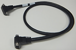
701982 Connection cable
- DLM Micro USB Cable
- 701982-01 Connection cable for DLM 1.0 m
- 701982-02 Connection cable for DLM 2.8 m

- Construction and verification of SENT communication system
- Accurate, reliable data transmission at low cost


While accurate rise time measurements have become easier to make, it remains, nonetheless, quite easy to overlook error contributions due to not only the oscilloscope but also the probe. And, while the error contributed by a scope's finite step-response (rise time) is often accounted for, that contributed by the probe is often overlooked.


DLM5000_Simultaneous_analysis_of_eight_CAN_buses


Frequency to Voltage Conversion Problem: A transducer produces a sine-wave output dependant on the voltage-input; here is how to decode that output with a scope or a ScopeCorder. For 3kV input, the transducer ...
The free software DL-GATE can be used for the following products only:DL1700E seriesDL7400 series (firmware version after 1.32)DL1600 series (firmware version after 1.13)DL750 series (firmware version after ...
The DLM series oscilloscopes (DLM5000HD, DLM5000, and DLM3000) and ScopeCorders (DL950, DL350) provide the CAN Bus symbolic decode analysis function. For DLM series, an overlay function displays the CAN packet structure directly below the time domain waveform.
Brochures
- DLM Series High Definition Oscilloscope/Mixed Signal Oscilloscope (9.2 MB)
- Probes and accessories for Oscilloscopes (2.2 MB)
Instruction Manuals
- DLM3034HD, DLM3054HD High Definition Oscilloscope Features Guide and User's Manual (16.0 MB)
- DLM3034HD, DLM3054HD High Definition Oscilloscope Features Guide (5.2 MB)
- DLM3034HD, DLM3054HD High Definition Oscilloscope USER'S MANUAL (11.0 MB)
- DLM3034HD, DLM3054HD High Definition Oscilloscope Getting Started Guide (7.4 MB)
- DLM3034HD, DLM3054HD High Definition Oscilloscope Operation Guide (1.6 MB)
- DLM3034HD, DLM3054HD High Definition Oscilloscope Communication Interface User's Manual (4.5 MB)
- Model 709813 Additional Option License for the DLM3000HD User’s Manual (308.3 KB)
Software
- Xwirepuller
- DL-Term
- Symbol Editor
- Mask Pattern Editor
- USB Drivers
- TMCTL
- MATLAB WDF Access Toolbox
- WDF File Access Library
- Communication Sample Program for DLM series
Firmware
Drawings
Product Overviews

Test and measurement engineering work groups can have differing priorities and requirements, which often results in multiple instrumentation systems and data file formats, as well as incompatible reporting. This lack of effective communication between groups and instruments causes decreased efficiency and quality and increased spending and time to market. Unify test and measurement instrumentation, software, and data across engineering teams with a suite of solutions that caters to the different needs of engineering work groups, including accurate power data, fast sampling rates, long recordings of multiple different input types, and insights into waveform data.

Webinars
- Establishing baselines for system efficiency
- Conducting inverter control signal analysis at the systems level
- Identifying critical measurements for benchmarking inverter input, inverter output, and motor output
- Analyzing motor control signals, including torque control variables, positional sensors, and pulse-width modulation (PWM), as well as torque measurements

With ongoing innovations in motor and inverter technologies seeking to advance global decarbonization objectives in the automotive industry, it’s crucial that engineers have a thorough understanding of how to properly analyze these systems.
This complimentary webinar provides engineering professionals involved in motor and control system development with insights that enable data benchmarking and troubleshooting issues related to energy efficiency in electric vehicle (EV) powertrains.
Key webinar topics include: