Power Meter Tutorials - Measurement
Yokogawa hopes that its Power meters contribute to a world with cleaner and more efficient energy use. The below tutorial intends to help with power measurement.
Measurement
- Energy saving
- Theory of electric power
- Measurement of mains interruptions
- Power and energy measurement applications
- Power measurement for energy saving equipment
Theory of Electric Power
What is Electric Power
- Definition: Power per 1 hour by using Electric Energy
- Image: Value of Energy to accomplish a Job such as Moving, Lighting and Heating
- Definition: A Work Load of Electric Energy

- At the case of actual DC driven equipment, input level of both DC voltage and DC current is not stable. Therefore, power measuring instrument is required to measure not only DC signal but AC input (transient signal).
AC power at the condition of sine wave

At the condition of sinusoidal inputs, AC Power is calculated by three parameters such as Voltage, Current and Phase Angle between those waveforms. The phase angle is decided theoretically depending on impedance of the load. Also, input frequency influences the error of power meter .
Impedance of ideal load is classified as below

Impedance of ideal load is classified as below:
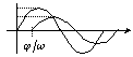
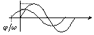
- Resistance (No phase difference between V&A)
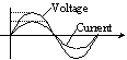
- Reactance (Phase of current is delay)
- Capacitance (Phase of current is forward)


Power Factor
Definition : Power ratio respected to inputted Apparent Power Relation among parameters of electric power(Single Phase)

Note: Power Factor Error
- Power Factor Error (Difference of delay of phase angle between voltage input circuit and current circuit)


- Total Error including Power Factor Error

Measuring Error of Power is calculated by summation of Voltage measuring error, Current measuring error and Phase angle error.

Distorted input(waveform)
Crest Factor : Ratio of PEAK value respected to RMS value


Crest Factor of measuring instrument and inputted waveform
- Inputted waveform : Characteristic of the waveform (measured by a function power meter)
- Measuring instrument : Specification(allowable Crest Factor) of power meter at condition of displaying range rated value on the DISPLAY
For example : Condition - 2Arms range setting and displaying 2Arms (range rated value)
If the specification of the power meter is CF=3, 2Arms*3=6Apeak distorted waveform is allowable to measure. So, if input is 0.2Arms(10% of the range), 6Apk/0.2Arms = 20 times is allowable to measure. In this case, CF is 20.
Power of distorted waveform
When voltage(also current) consists of DC component, fundamental component and many harmonic components, the waveform is expressed as below;

In this condition, Power of the distorted waveform is the sum of effective power of identical frequency components contained in Voltage and Current as below;

Therefore, if voltage and current waveforms and those frequency components are showed as below figure, Power is calculated by using limited frequency components of Current frequency range(narrower frequency range) . Narrower bandwidth is enough.


RMS and True RMS
True RMS(RMS calculation) :AC voltage or AC current value which occurs same Power consumption as DC voltage/current value when it is inputted to pure resistance. For example, 1Vrms and 1Vdc can occurs same energy. The expression is as below.

RMS(Rectified Mean calculation) : Low cost measurement or calculation method to get same value as True RMS method at the condition of sinusoidal input. The expression is as below.

When sinusoidal is inputted, there is no difference of result between RMS and True RMS. However, if it is distorted waveform, calculation result is different. It is problem.
In Japan, JEMA(Japanese Electric Machinery Association) decided to use RMS(Rectified MEAN) calculation method to measure out put voltage of PWM type Inverter. Because the value is proportional to torque output of its driven motor. It is important for their specification.
Measurement of Three Phase Power
Three Phase Electric Power can be calculated to sum of each power value by using separated three power meters.
Also, Theory of Brondel said that n-phase electric power can be measured by using n-1 units of power meters. Therefore, three phase power is measured two power meters. The method is called two power meters method and is popular in Japan.
- Three phase three wire system (measurement of 3 voltages, 3 currents)
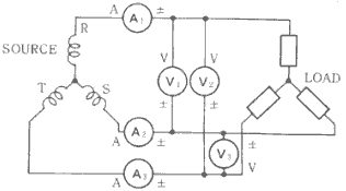
- Three phase three wire system (measurement of 2 voltages, 2 currents)
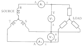


Wrong wiring (It occurs frequently.)
Influences of high frequency common mode voltage of Inverter driven motor (It requires know-how to solve depending to the case.).
Tractability of Power

Power and Energy Measurement
Switching Mode Power Supply
Switching Mode Power Supply is adopted to almost Household Appliances and Office Automation Equipment
The inputted current waveform is distorted like pulse wave and also voltage waveform is distorted same point as current. It includes so much harmonic components because of circuit design of capacitor input style.

Requirements for Power Meter;
- Accurate measurement in case of large Crest Factor waveform
- Wide frequency bandwidth up to components of distorted input waveform
- Accuracy and Linearity in case of small current input
Inverter Driven Motor
Type of Inverter : PWM is main method and PAM becomes popular
PWM(Pulse Width Modulation) : Revolution speed of motor is controlled by using change of pulse width of voltage waveform. And there are two types of method in PWM. One is Sinusoidal PWM and another is Square-wave PWM. The Sinusoidal or Square- mean current waveform of motor input.

PAM(Pulse Amplitude Modulation) : Revolution speed is controlled by amplitude of voltage. And the waveform both voltage and current are square. Therefore, frequency bandwidth of measuring instrument for current is required higher than PWM type inverter.

Requirements for Power Meter;
- Immunity against large and high frequency common mode voltage
- Broad frequency bandwidth from DC to components of square waveform
High frequency fluorescent Lamp
Inverter for high frequency fluorescent lamp
In general, the waveform is a kind of triangle or sinusoidal. And the fundamental frequency is below 100kHz. Also envelope is twice of commercial frequency.

Requirements for Power Meter;
- Immunity against large and high frequency common mode voltage
- Broad frequency bandwidth from DC to components of carrier frequency
- Small loss of instrument(high impedance of voltage input and low impedance of current input
Energy(Watt-hour) Measurement
Measuring method of fluctuating Electric Power (for example : Copying machine)
Requirement of Power Meter ;
- igh Accuracy and Linearity from small to large power at one range
- High speed response time according to steep input waveform
Variety of Power Measuring Instruments
Inductive Type Wh-meter
Inductive Type Wh-meters, which are based upon the principle of mechanically averaging instantaneous power measure electrical energy consumed in a home for billing purposes. It is guaranteed only commercial frequencies 50/60Hz.

1: current coil 2: Short ring
3: Movable disk 4: Phase adjusting coil
5: magnetic shunt steel 6: manganin resistor
7: Secondary voltage coil 8: Voltage coil
Analog indicate type Power Meter
Principle : Repulsion of magnetic field caused by currents of both Fixed and Moving coils


- Frequency bandwidth(It can not measure component upper than 400Hz accurately.)
- Dynamic ranges and accuracy especially in the case of small input
- Immunity against large input current

Analog calculation type Digital Power Meter
Principle : Time Division Multiple analog circuit method Multiplication circuit
 Waveform

Restrictions ;
|

YOKOGAWA 2533 |

Digital Sampling type Digital Power Meter
Principle : Digital filtering method of digital sampled data


Restrictions ;
|

YOKOGAWA WT2000 |
Power Measuring Technique for Energy Saved Equipment
Measuring Accuracy of very small current and power
We are afraid that we can not receive any standard calibration for small power(small current condition) below to 1W(at standby mode of electric equipment) in Japan at present time. Official Calibration Lab, JEMIC(Japanese Electric Machinery Inspection Corporation) can calibrate below to 10W only. Therefore, Yokogawa tried to show the guideline of accuracy for small power as blow. It consists of summation of Voltage error, Current error, Phase angle error and special calculation error of the power meter.

Also, all WT series can measure small current below to 2 or 3% of the range rated value as below graph. (It shows 500mA range of WT110.)
An example of linearilty error (0.5 A range)

Wiring technique for Reduction of Instrument Loss
We should pay an attention of reduction for the Instrument Loss in case of low power measurement below to approx. 0.5W. It causes of impedance of voltage input circuit. If the impedance is 1M ohm and 240 V input, it influences +0.058 W, more than 10% of target.
In such case, we should check the Wiring Method described in the Instruction Manual as below;
Recommended Wiring method for small current measurement


Distorted Waveform(Crest Factor)
When current waveform is distorted and has big Crest Factor characteristic like condenser input type switching mode power supply, measuring current range should be selected properly. Otherwise, measured value is not accurate because peak part of the waveform is neglected or bigger current range is selected.
In such case, Energy Star Program decides to set proper range after measuring peak current and selecting suitable range.

 |
Object : TV, VTR, PC Printer, Copying Machine, FAX Machine |
Wh measurement for equipment with fluctuating power
When trend of power(or current) level is fluctuated as below figure, some power meters can not detect and measure small or rapid change of power(or current). Especially, it influences Watt-hour(Integration) measuring function. Therefore, we should check lower limit and response time of power meter before use it. Refrigerator, PC


Measuring Bandwidth
Generally speaking, voltage and current waveforms of electric equipment are distorted recently. Therefore, broad measuring bandwidth is required.
In order to measure target within 0.1% accuracy, triangle waveform requires measuring bandwidth by 5 times to the fundamental frequency and 200 times or more for square waveform theoretically. Also measuring accuracy at the high frequency should be paid an attention.
However, frequency bandwidth depends on the bandwidth of lower frequency parameter as explained in this document. Therefore, frequency bandwidth is not first priority for distorted waveform.
 |
 |

Influence of Common Mode Voltage
Common Mode Voltage ; It locates between earth ground and target equipment and oscillated voltage is added to both Hi and Lo terminals commonly.
If impedance between Hi terminal loop(R1+Z1) and Lo terminal loop(R2+Z2) are different, current becomes different in the two loops and it occurs differential voltage between input terminals and causes measurement error.

| Voltage input terminals are shorted and connected one line of target. And current input terminals are opened and connected one line as right figure. The influence appears as measurement value according to below expressions.
|
 |

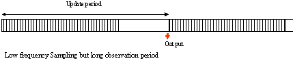
Averaging method by using AVE function
Some equipment using intermittent operation(or control) method in order to reduce power consumption at standby mode requires long period measurement and averaging function till next oscillate as below figure.
Generally, power measuring instrument has settled measuring period and update cycle. Therefore, it should be set the longest period setting when it measure such equipment. And if it is not enough, averaging function should be set on.
It is important to set averaging period according to input waveform like PZ4000.


YOKOGAWA PZ4000
Observation period of input signal
- Oscilloscope (Digital Sampling Method)
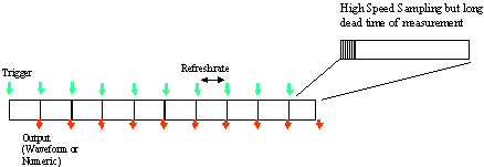
- Power Meter(Both Analog calculation and Digital Sampling method)


Related Products & Solutions

WT2010/WT2030 Digital Power Meters
The WT2000 digital powermeter series has been designed with emphasis on basic performance (bandwidth, accuracy, response speed, and noise immunity) from the viewpoint of measurement of electrical quantities. The broad range of functions of these power analyzers enable them to be used in various fields of applications.