Harmonics Measurement for Low-Voltage Distributed Generation

1. Introduction
In recent years, equipment with a switching power supply has entered widespread use and sometimes causes waveform distortion of currents flowing to power grids, resulting in grid system instability and other failures. To prevent such failures, there are strict regulations on harmonic currents in electrical and electronic equipment. Meanwhile, many countries and companies are working toward carbonneutral goals, which is leading to an increase in the amount of power generated from distributed renewable resources.
Harmonic currents also need to be suppressed from the perspective of power quality control.
2. Challenges
Harmonic currents are regulated internationally under IEC standards as well as under country- and field-specific rules, so measuring instruments must be designed with the flexibility to meet the requirements of these standards and rules. And with the percentage of power generated from renewable energy sources as a share of the total power supplied increasing, it has become more important for gridconnected low-voltage distributed power generation systems to suppress harmonic components. As a result, detailed new rules have been established to regulate interharmonics between each order of 50/60 Hz.
IEC 61000-3-2, which is one of the harmonics control standards, has been regulating harmonic currents in the low-frequency range up to 2 kHz or 2.4 kHz to date. In addition to this, regulatory rules are being considered for controlling harmonic currents in the frequency range of 2 kHz to 9 kHz, which is intermediate between the said low-frequency range and the frequency range of 9 kHz and higher (noise region).
In these situations, there is an increasing need for relevant manufacturers and organizations to measure and analyze frequency components in this frequency range. Reflecting this background, the typical harmonics analysis involves measurements of the following items:
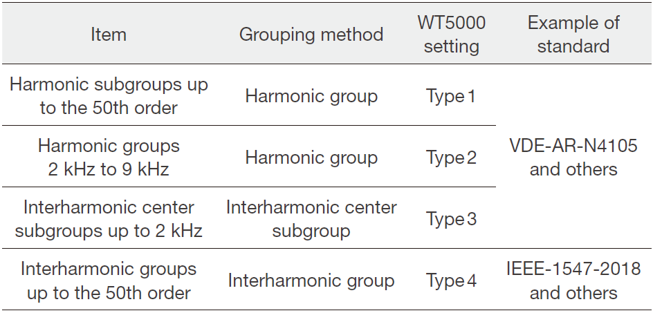
Table 1. Regulatory standards and WT5000 settings for harmonic currents of low-voltage distributed power generation systems
3. Solutions provided by WT5000 and IS8000
- Power measurement with the best-in-world level accuracy
- Harmonics and flicker tests compliant with IEC standards
- Measure harmonic for each order and total harmonic distortion (THD)
- Type 1 to 4 setting for harmonic/interharmonic grouping
- Harmonic subgroups up to the 50th order (Type 1)
- Harmonic groups in the range of 2 kHz to 9 kHz (Type 2)
- Interharmonic center subgroups up to 2 kHz (Type 3)
- Interharmonic groups up to the 50th order (Type 4)
- Analyze waveform data using the data streaming function
4. Grouping for Measuring Harmonics
4.1 Measuring harmonics up to the 50th order with their interharmonics (Type 1)
Harmonics are sine waves with frequencies that are integer multiples of the frequency of the fundamental sine wave, which is a commercial frequency of 50 Hz or 60 Hz, and refer to components of orders other than the fundamental wave.
For example, when the fundamental wave (1st component) is 50 Hz, the 3rd component has a frequency of 150 Hz, the 5th component has a frequency of 250 Hz, and so on. These harmonic components are superimposed to create a distorted waveform (see Figure 1). The international standard for harmonic current regulations stipulates limits for harmonic current up to the 40th order for equipment with a current of 16 A per phase or less, categorizing the equipment into classes A/B/C/D depending on the equipment.
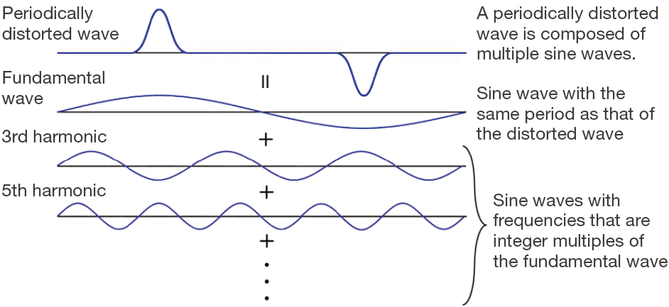
Figure 1. Principle of harmonics (superposition principle)
Interharmonics, which are present between two consecutive harmonics, must also be suppressed. When an input signal has a frequency of 50 Hz, 10 cycles of the input signal are Fourier transformed and decomposed into frequency components with 5 Hz resolution, generating 10 frequency components of interharmonics. The 10 components thus generated between two consecutive harmonics are interharmonics of the 50 Hz input signal (see Figure 2). When an input signal has a frequency of 60 Hz, 12 cycles of the input signal are decomposed into frequency components with 5 Hz resolution. As a result, there are 12 frequency components between each harmonic order.
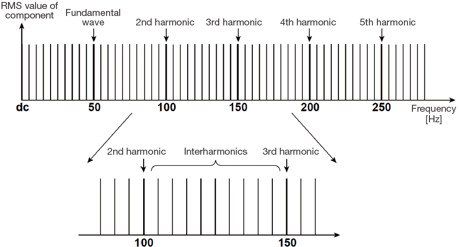
Figure 2. Interharmonics (for a 50 Hz fundamental wave frequency)
The harmonics regulation standards require harmonic components to be grouped for evaluation. A harmonic group is composed of a harmonic and interharmonics adjacent to it. The calculation method for summing the total value of a harmonic and its adjacent interharmonics is to square each component, add them together and then take the square root (Root-Mean-Square), rather than simply adding them together, since these components are RMS values. Be sure to note here that for an interharmonic component exactly at the midpoint between two consecutive harmonics, one half of its RMS value is included in the calculation.
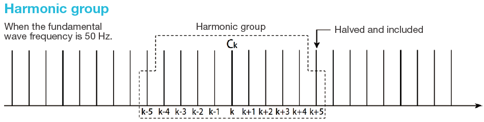
Figure 3. Harmonic group (for a 50 Hz fundamental wave frequency)
Furthermore, there is also a group called “harmonic subgroup,” which comprises a harmonic and the two interharmonics immediately adjacent to it. The RMS sum for this subgroup is calculated by taking the square root of the sum of squares, as in the case of a harmonic group.
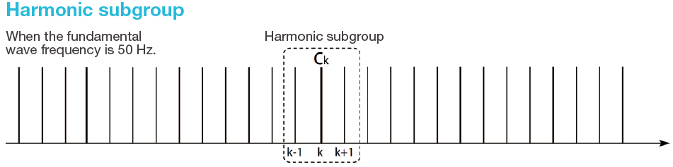
Figure 4. Harmonic subgroup (for a 50 Hz fundamental wave frequency)
Meanwhile, there are country-specific rules on small-scale distributed power generation using solar, wind, and other renewable energy sources, and they regulate harmonics up to the 50th order, not up to the 40th order. In response to this, the WT-series power analyzers are designed to accommodate measurements of harmonics up to the 50th order or higher.
4.2 Measuring harmonics in the range of 2 kHz to 9 kHz (Type 2)
The WT5000 Precision Power Analyzer is designed to accommodate measurements of harmonics in the frequency range of 50 Hz to 10 kHz so it can measure harmonics in the frequency range of 50 Hz to 2.5 kHz as before, and also measure harmonics in the frequency range of 2 kHz to 9 kHz.
This is achieved by increasing the number of orders of harmonics that can be measured from the 50th order (50 Hz × 50 orders = 2.5 kHz) to the 200th order (50 Hz × 200 orders = 10 kHz), and accordingly increasing the sampling frequency for harmonics measurement so that there are 32,768 sampling points in one window (ten cycles of the fundamental wave). The grouping for harmonics from 2 kHz to 9 kHz is slightly different from other cases, so it is shown in Figure 5.
Grouping OFF (no grouping) and harmonic subgroups are the same as other cases, but the harmonic groups are slightly different. Figure 5 illustrates grouping of the 2100 Hz harmonic component as an example. The calculation for the harmonic group at 2100 Hz excludes the 2000 Hz harmonic component, includes the interharmonic components that are higher than 2000 Hz and lower than 2200 Hz, and includes the 2200 Hz harmonic component.
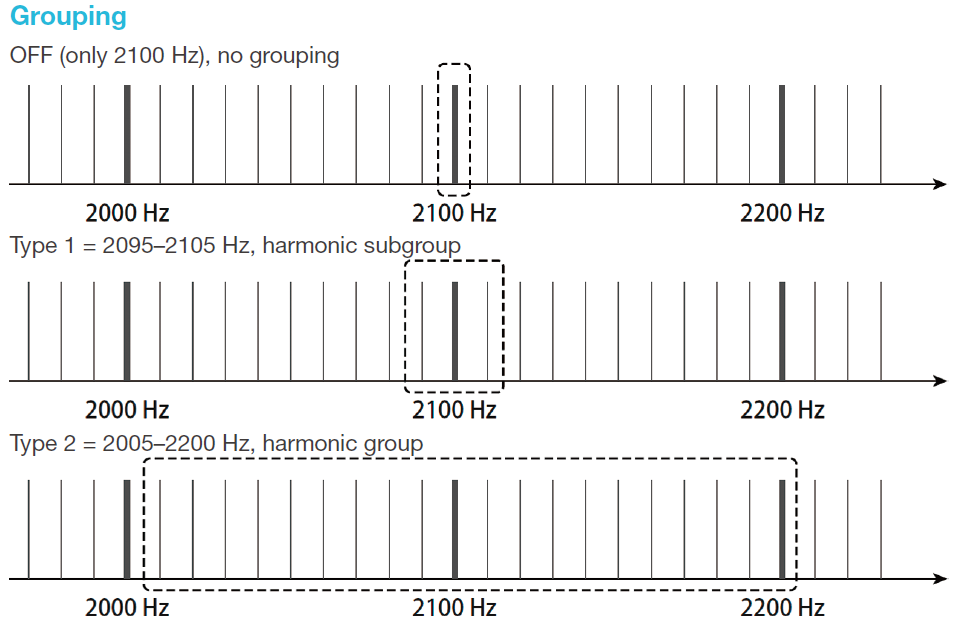
Figure 5. Grouping of 2 kHz to 9 kHz harmonics (e.g. 2100 Hz)
4.3 Interharmonic center subgroups up to 2 kHz (Type 3)
In some countries or fields, there are strict rules that regulate interharmonics as well as harmonics. There are also particular rules that regulate only interharmonic components excluding the above-mentioned harmonic subgroup, which comprises a harmonic and the interharmonics immediately adjacent to it. This necessitates grouping of these interharmonic components into a so-called interharmonic center subgroup. As shown in Figure 6, calculation of the RMS sum for this subgroup includes all interharmonic components between two consecutive harmonic frequencies, excluding frequency components directly adjacent to the harmonic frequencies.
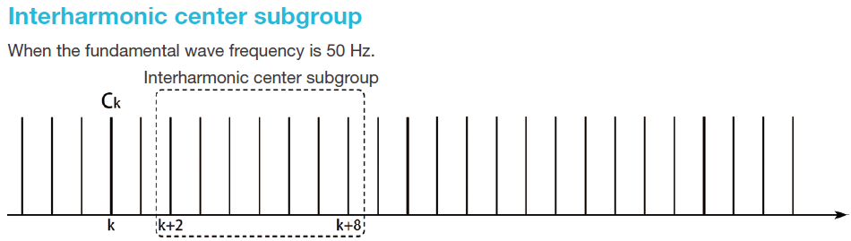
Figure 6. Interharmonic center subgroup (for a 50 Hz fundamental wave frequency)
4.4 Interharmonic center groups up to 2 kHz (Type 4)
Apart from the above, the WT5000 can calculate the RMS sums for interharmonic center groups up to the 50th order.
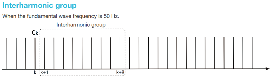
Figure 7. Interharmonic group (for a 50 Hz fundamental wave frequency)
With the WT5000, you can specify the harmonic grouping type on the IEC Harmonic menu screen as shown in Figure 8.
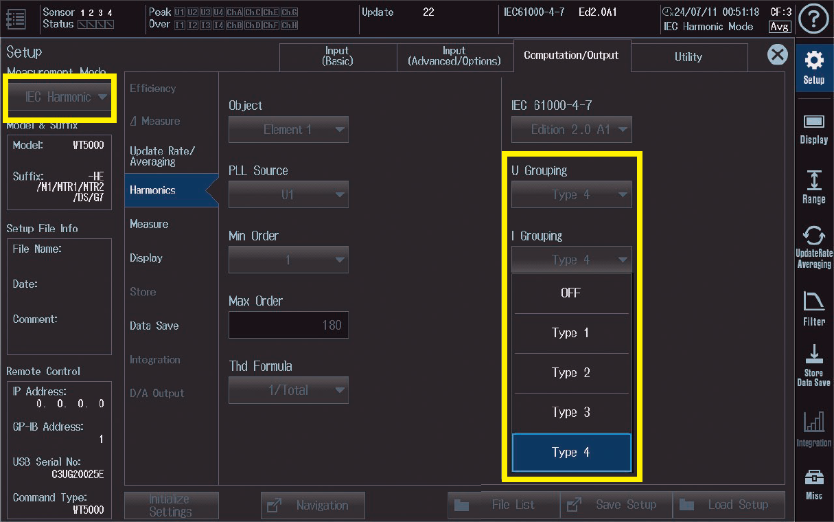
Figure 8. Type setting on the WT5000 main unit for harmonics measurements
5. Examples of measurement and display provided by IS8000
5.1 WT5000 harmonics measurement menu on the IS8000
By using the WT5000 together with the PC application software, IS8000 Integrated Software Platform, you can view the results of measuring harmonics/interharmonics up to the 50th order or the results of measuring harmonics/ interharmonics in the frequency range of 2 kHz to 9 kHz on a PC screen and save the measurement data.
The DAQ (IEC 2 kHz–9 kHz) menu on the IS8000 menu screen provides access to the harmonics/interharmonics measurement function as shown in Figure 9.
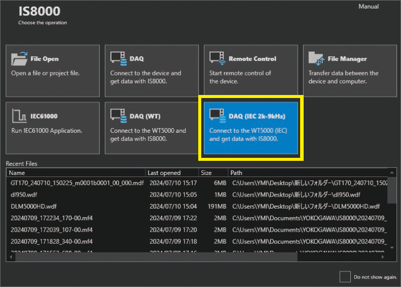
Figure 9. IS8000 menu screen
5.2 Setting the harmonics/interharmonics measurement parameters
The IS8000 basically shows numerical data graphically as waveforms. The function of measuring harmonics and interharmonics in the newly added frequency range is accessed from the 2 kHz to 9 kHz harmonics measurement menu. Therefore, waveform data parameters for voltage/ current harmonics default to the values preset for the harmonic with a frequency of 2100 Hz. Before measuring a harmonic of a different order, you need to add its harmonic parameters or changing the values preset for the 2100 Hz harmonic to those for the harmonic to be measured (see Figure 10).
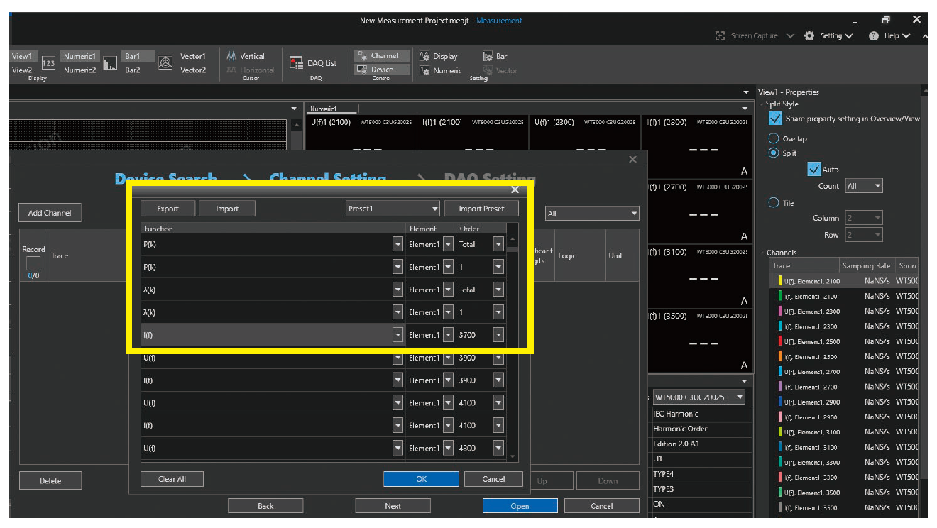
Figure 10. Example of setting waveform (graph) data parameters
You also need to set its numerical value display parameters by changing the values preset for the 2100 Hz harmonic to those for the harmonic to be measured, as in the case of the waveform (graph) data parameters (see Figure 11).
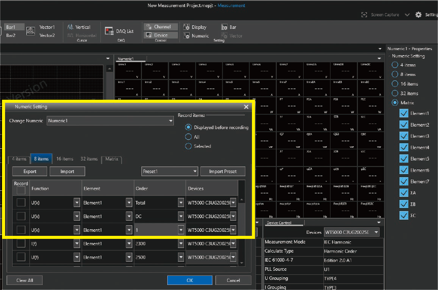
Figure 11. Example of setting numerical parameters
5.3 Examples of measuring harmonics/ interharmonics
Figures 12 to 14 show the results of measuring harmonics/ interharmonics by using Type 3 and Type 4 groupings, new additions to the grouping function, and an example of measuring harmonics/interharmonics in the frequency range of 2 kHz to 9 kHz (Type 2).
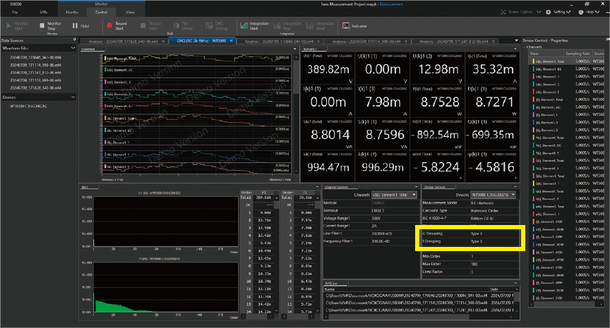
Figure 12. Interharmonic subgroups up to 2 kHz (Type 3)
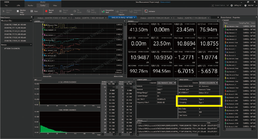
Figure 13. Interharmonic groups up to 2 kHz (Type 4)
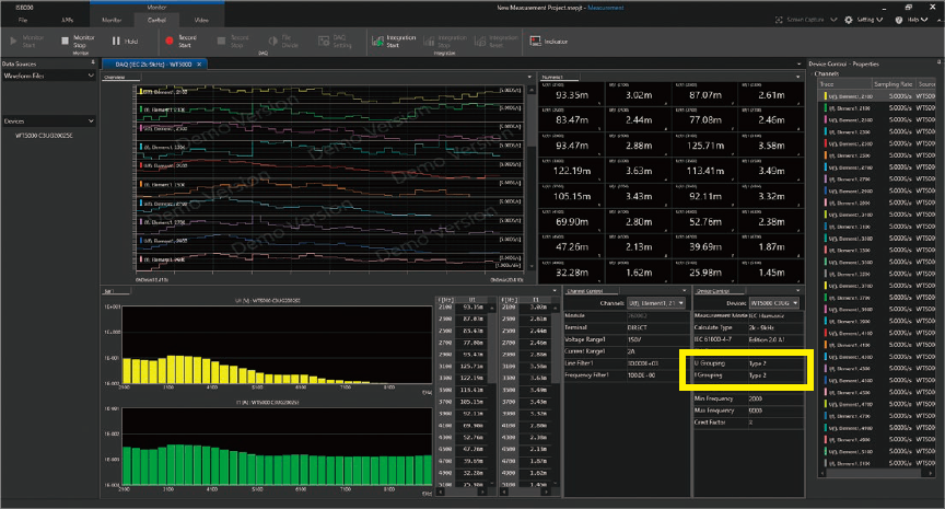
Figure 14. Measurement of harmonics in the range of 2 kHz to 9 kHz (Type 2)
Related Industries
Related Products & Solutions

IS8000 Integrated Software Platform
- IS8000 Test- und Messsoftware zur Integration von Daten
- Schnelle Daten für eine effiziente Produktentwicklung
- Synchronisierte Messungen
- Zusätzliche Software-Pakete

WT5000 - Präzisions-Leistungsanalysator
Der Präzisions-Leistungsanalysator WT5000 definiert die neue Referenz in der Leistungsmesstechnik mit einer aktuell weltweit höchsten Grundgenauigkeit von ± (0,01 % des Messwerts + 0,02 % des Effektivwert-Messbereichs). Jedes erdenkliche Anwenderszenario wird durch die modulare Bauweise (Self-Service) sowie durch die mögliche Kaskadierung realisiert: bis zu 28 Leistungsmesskanäle plus 16 Motoreingänge gewährleisten vollumfängliche Messungen. Die neue „Digital Parallelpfad-Technologie“, wie auch die Harmonischen-Analyse (bis zur 500. Ordnung) runden den Leistungsumfang ab.

