Multi-Grid Power Conditioner Measurement for Mega Solar Systems

1. Introduction
In solar power generation systems, a power conditioner (also referred to as an inverter or PCS) is used to convert the generated DC power into AC power. The degree of conversion efficiency (conversion loss) is an indicator of how competitive a product is in the market. Generally, power conditioners for large-capacity solar power generation systems, such as mega solar plants, need to simultaneously handle multiple inputs/outputs of several hundreds of kilowatts to several megawatts.
When connecting multiple grids, there are two methods: a large-capacity power conditioner with multiple inputs and outputs is connected to the grids, and small-capacity power conditioners that are arranged in parallel and connected to the grids. In either case, measuring the input-output efficiency with a high degree of precision is crucial.
Systems that generate power using renewable energy sources, such as sunlight, are likely to be affected by weather. Therefore, it is necessary to assume grid instability due to a sudden increase in the amount of power generated, reduced power quality due to a lightning strike on a grid, and other possible situations caused by weather conditions.
For this reason, power efficiency evaluations are conducted through voltage fluctuation tests, frequency fluctuation tests, temperature-rise tests, and various other tests that involve not only power measurements using power meters but also observations of instantaneous waveform fluctuations and time-series temperature trend measurements using waveform measuring instruments.
2. Challenges
There is demand for power measuring instruments that can accurately detect fluctuations in active power, reactive power, voltage, frequency, power factor, efficiency and other power parameters even in situations such as a sudden change in weather. To measure a power conditioner connected to multiple grids, it is necessary to use a power measuring instrument that has a high degree of reliability and multiple measuring channels.
In addition, it is necessary to use a waveform measuring instrument to continuously monitor a grid for a long time and detect instantaneous fluctuations. This instrument must have multiple measuring channels, just like a power measuring instrument, also be capable of measuring waveforms at high sampling rates while acquiring the minimum amount of data.
For example, when a general measuring instrument is used for simultaneously measuring a voltage that changes quickly and a temperature that changes relatively slowly, it needs to measure both quantities at the higher sampling rate specified for the higher-speed signal. Meanwhile, there are cases where results of a power measurement performed by a waveform measuring instrument cannot be used as reliable data. To overcome these problems, the industry needs a way to measure power values with a highly reliable power measuring instrument while analyzing data with a waveform measuring instrument synchronized with the power measuring instrument.
3. Solutions provided by WT5000 and DL950
• Utilizing highly reliable, highly accurate power data
• Multi-channel power measurement with high flexibility in wiring configurations
• Simultaneous measurement of various physical quantities and transient power
• Reducing the amount of data by using multi-sample rate
• Synchronized monitoring with five measuring instruments combined with the IS8000
4. Proposals provided by WT5000 and DL950
4.1 Utilizing highly reliable, highly accurate power data
The WT5000 Precision Power Analyzer is the world’s most accurate power measuring instrument, with a basic power accuracy of ±0.03%. Yokogawa’s power analyzers, including the WT5000, have established and maintain highly precise measurement standards compliant to national standards and ensure reliable measurements of voltage, current, active power, and other power parameters.
In recent years, there is an increasing number of waveform measuring instruments equipped with a power calculation function to ensure data simultaneity even in transient phenomena. While these instruments are convenient, you should check that the accuracy of calculated power values is guaranteed in line with the national standards.
The main purpose of a waveform measuring instrument is to capture the waveforms of measured signals more accurately with high bandwidths and at high sampling rates by using voltage and current probes. Consequently, power values calculated by a waveform measuring instrument often differ from those measured by a power meter and provide no guarantee of accuracy, necessitating thorough verification of reliability.
Reference: For more information on the calibration technology that guarantees the performance of the WT5000, refer to the following White Paper:
https://cdn.tmi.yokogawa.com/1/8690/files/Yokogawas_power_calibration_ technology_to_support_high-precision_power_analyzer.pdf
4.2 Creating a multi-channel and highly flexible power measurement system
Equipped with up to seven input channels, you can use the WT5000 for multi-channel measurements of power conditioners for mega-scale solar power generation systems. The seven input channels provide great flexibility in wiring configurations, enabling you not only to measure signals of seven DC inputs but also to measure signals of two 3-phase AC power and one DC inputs. Thanks to modular architecture, the input elements of the WT5000 can be added or changed easily to alter the maximum current input. As one example, you can measure one 3-phase power signals using three input elements right after getting the WT5000 main unit, and afterward, can also measure one single-phase power signal by obtaining one more input element and adding it to the WT5000.
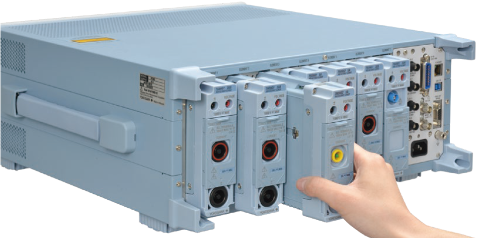
Figure 1. Changing WT5000 input elements
Yokogawa offers three types of input elements designed for different types of input: 5 A element, 30 A element, and dedicated element for current sensor. The combination of input elements is easy to change without any timeconsuming modification. This ensures great flexibility when using the WT5000 for power measurements.
4.3 Simultaneous measurement of various physical quantities and transient power
The DL950 ScopeCorder is a waveform measuring instrument that has modular architecture, just like the WT5000, and enables you to select up to eight modules from a wide variety of them. Examples are the 701265 Temperature/ High-Precision Voltage Module and the 720221 16-CH Temperature/Voltage Input Module, which can be used to measure temperatures, and the 720281 Frequency Module, which can be used for measuring frequencies. By employing a single DL950 unit equipped with these modules, you can measure multiple physical quantities simultaneously with a voltage waveform.
In addition, using the DL950 equipped with the Power Math Function (/G05 option) allows you to analyze transient power data. By combining the DL950 (/G05) with the IS8000 as described later, you can simultaneously monitor the transient response in waveform while measuring accurate values with the WT5000.
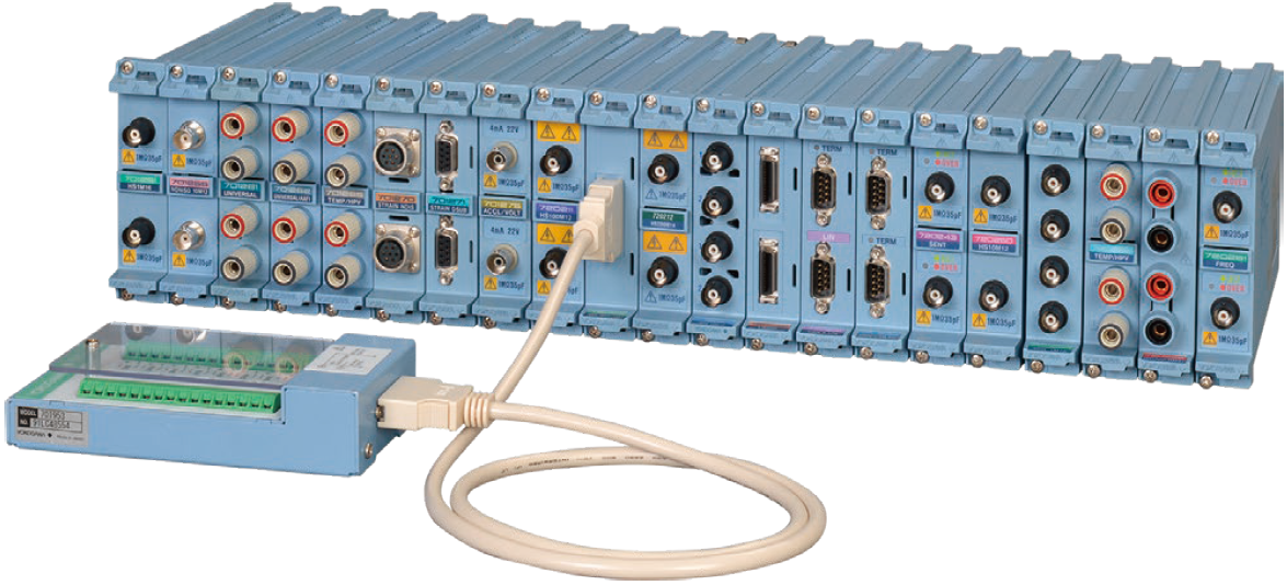
Figure 2. Various kinds of modules for ScopeCorder
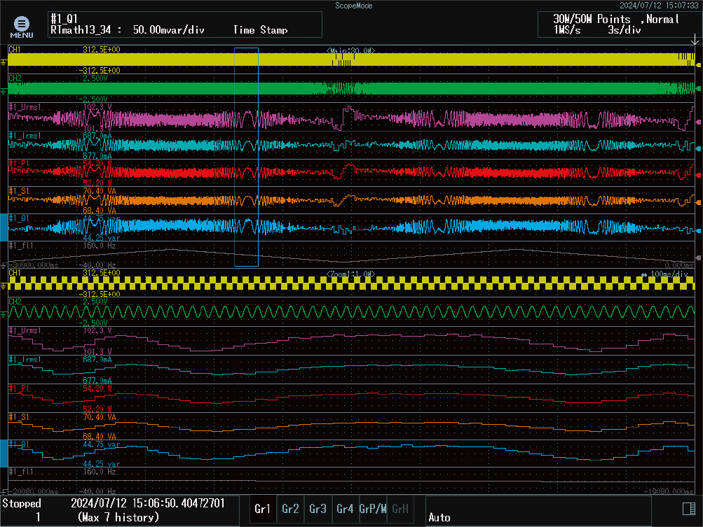
Figure 3. Example of power analysis screen on the DL950 (/G05)
4.4 Reducing the amount of data by using multi-sample rate
When using a waveform measuring instrument to perform a multi-channel measurement, it is necessary to specify a sampling rate that ensures the instrument will not miss the highest-speed signal. For example, in simultaneous measurement of a temperature and a voltage where the former changes more slowly than the latter, unnecessary data accumulates as the duration of the measurement becomes longer. The DL950 solves this problem by using multi-sample rate.
As shown in the figure below, by sampling slowly fluctuating signal at a slower rate, which would normally be interpolated to match the fastest sampling rate, the amount of data is reduced. This will help to operate with an optimized data size.
This multi-sample rate is effective not only for saving data in binary files but also for saving data in ASCII files. If data is output to a CSV file, the amount of data is reduced by making everything other than the actual sample data into spaces.
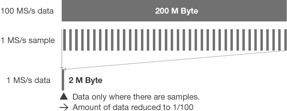
Figure 4. Reducing the amount of data by using multi-sample rate
4.5 Synchronized monitoring with five measuring instruments combined with the IS8000
As described so far, both the WT5000 and the DL950 can be powerful tools for measuring power conditioners connected to multiple grids. This section explains the integration of measurement data using the IS8000 Integrated Software Platform.
The IS8000 allows and facilitates synchronized measurement by synchronizing the DL950 and the WT5000*1. This highprecision synchronization between the DL950 and the WT5000 is based on the IEEE 1588 standard,*2 and the synchronization error between them is approximately 10 μs.*3
This makes it possible to analyze the results of a highprecision power measurement, transient power fluctuations, and voltage/current waveforms along the same time axis.
*1 Requires IS8000 Multi-Unit Synchronization (/SY1 option) for synchronized measurement using two or more units.
Requires the DL950 IEEE 1588 Master Function (time synchronization) (/C40 option).
*2 IEEE 1588 standard: A Precision Time Protocol (PTP) used to synchronize time between devices connected on a network.
*3 The IEEE 1588 synchronization error between two DL950 units is within 150 ns
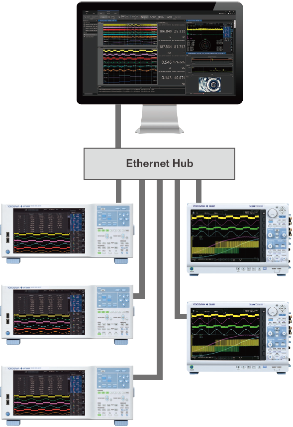
Figure 5. Example of connecting instruments for multi-unit measurement*
* Requires the PTP/IEEE 1588 grand master for high-precision time synchronization between two or more units.
* The images shown here may differ in part from the actual products.
* The specifications of this application may be restricted depending on the number of channels, measuring conditions, and other factors. Contact us for more information.
5. Other Multi-Channel Measurement Products
Features of the DL950 ScopeCorder
• Isolated input of up to 1000 V
• 200 MS/s high-speed sampling
• A variety of plug-in modules and integrated measurements
• Real-time mathematical computation
• High noise resistance
• Trend display for in-vehicle serial buses
• Simultaneous measurements of up to 32 channels with one unit
* When installing 4 channel modules in 8 slots
• Multi-unit connection up to 5 units
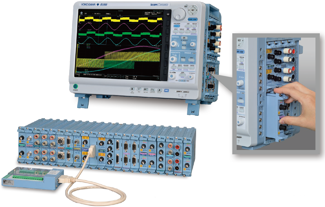
Figure 8. DL950 ScopeCorder and modules
Related Industries
Related Products & Solutions

DL950 ScopeCorder
Capture and analyze a wide variety of electromechanical signals and serial buses. High sample rate, long recording times, advanced triggers, and real-time analysis.

IS8000 Integrated Software Platform
- IS8000 Test- und Messsoftware zur Integration von Daten
- Schnelle Daten für eine effiziente Produktentwicklung
- Synchronisierte Messungen
- Zusätzliche Software-Pakete

WT5000 - Präzisions-Leistungsanalysator
Der Präzisions-Leistungsanalysator WT5000 definiert die neue Referenz in der Leistungsmesstechnik mit einer aktuell weltweit höchsten Grundgenauigkeit von ± (0,01 % des Messwerts + 0,02 % des Effektivwert-Messbereichs). Jedes erdenkliche Anwenderszenario wird durch die modulare Bauweise (Self-Service) sowie durch die mögliche Kaskadierung realisiert: bis zu 28 Leistungsmesskanäle plus 16 Motoreingänge gewährleisten vollumfängliche Messungen. Die neue „Digital Parallelpfad-Technologie“, wie auch die Harmonischen-Analyse (bis zur 500. Ordnung) runden den Leistungsumfang ab.

