SL2000 High-Speed Data Acquisition Unit


The SL2000 is a high-speed, modular data acquisition system that combines the functionality of an isolated oscilloscope with the flexibility of a high-speed DAQ, ideal for design validation, ATE systems and operational testing.
Compatible with the same plug-in modules as the DL950 ScopeCorder, the SL2000 offers exceptional versatility for mixed-signal measurement. A single unit can simultaneously capture a wide variety of signals, including high voltages, vehicle communication busses, and NVH inputs such as vibration, strain, and temperature.
Key specifications:
- Isolated 1000 V input, up to 7000 V input with differential probe
- Up to 200 MS/s sampling
- Up to 8 G point memory
- 10 Gbps PC streaming
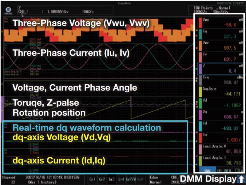
- Real-time power and motor d-q analysis
 Engineered for ATE Systems
 Engineered for ATE Systems
The SL2000 is a 4U-high, high-speed data acquisition system and modular isolated oscilloscope designed for high-channel-count automated testing and validation.
By integrating a wide range of plug-in modules, the SL2000 enables both transient capture and long-duration, multi-channel recording of diverse signal types including voltage, current, temperature, acceleration, strain, frequency, digital I/O, and automotive communication protocols such as CAN, CAN FD, LIN, and SENT.
Two Operation Modes: Scope and DAQ
Scope Mode: For high speed, repetitive signals. Works like an oscilloscope:
- Captures waveforms on trigger using T/Div and sampling settings
- Displayed with V/Div scaling
DAQ Mode: For long-duration, continuous recording. Functions like a data logger:
- Records with defined sampling intervals and total duration
- Displayed using absolute upper and lower limits
Scalable to 160 channels with IS8000 software
Capture signals at speeds up to 200 MS/s, and scale to 160 synchronized channels (/C50) by linking as many as five chassis as a single triggered unit.
Even higher channel counts are possible through custom integration.

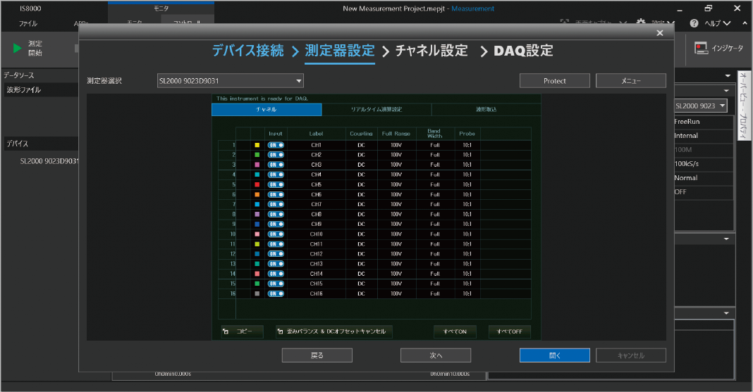
Flexible Control Software Options for Test Automation
Choose the approach that fits your workflow. IS8000 software offers a no-code, configurable solution for rapid instrument setup, data capture, and visualization, ideal for standardized test environments and where ease of use and long-term supportability are key.
For fully customized systems, Yokogawa's open API and sample code enable seamless integration into your bespoke ATE software for precise control and data streaming.
Advanced Real-Time Analysis
With optional functions such as real-time math (/G03), power calculations (/G05), and motor dq analysis (/MT1), the SL2000 can perform on-the-fly waveform computation, power analysis, and motor control vector analysis. Trigger conditions can also be set based on computed math results.

The SL2000’s capabilities are organized into five key groups to support high-throughput, automated test applications. Designed for flexibility, speed, and precision, each function accelerates workflows in demanding validation and production environments.
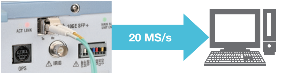 High-Bandwidth Data Streaming
 High-Bandwidth Data Streaming
The SL2000 delivers continuous, high-speed data transfer for real-time integration with automation software and test orchestration platforms.
- 20MS/sec streaming to PC over 10 GbE of raw and computed waveforms
- Free-run or triggered streaming via SDK over USB, Ethernet, or 10 GbE
- Open SDK access for C, Python, MATLAB, and LabVIEW environments
- No-code Yokogawa IS8000 software for ready to run testing
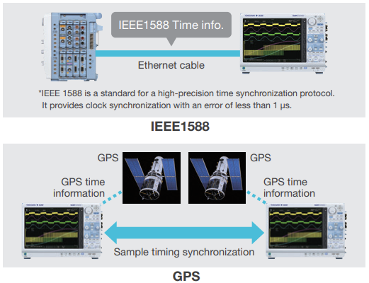 Scalable, Synchronized Systems
 Scalable, Synchronized Systems
For high channel count systems or multi-instrument testbeds, the SL2000 offers precise synchronization and seamless scaling.
- Multi-chassis expansion: up to 160 channels across 5 synchronized SL2000 units (timing skew within ±30 ns)
- Support for IEEE1588 PTP, IRIG, and GPS timing options enables synchronization across distributed or mobile setups
- IS8000 platform integration for synchronization with cameras, power analyzers, and external gear
Versatile Inputs
Supporting a wide array of sensor types and signals, the SL2000 is highly adaptable to various test configurations.
- Modular input architecture: accommodates up to 8 plug-in modules
- Analog inputs: voltage (up to 200MS/sec at 14 bits), current sensors, strain, temperature, vibration, and more
- Logic and digital inputs: digital logic, serial bus payload decoding & measurement (CAN, CAN FD, LIN, SENT)
- High-voltage inputs (1kV direct / 7kV with differential probe) and isolation for battery, inverter, and power-stage testing
Extensive Trigger Library & GO/NO-GO Logic
Sophisticated triggering and automated test decisions help streamline pass/fail evaluation and event-driven acquisition.
- Flexible trigger modes: Auto, Normal, Single, On-Start, and time-based triggers
- Trigger from any source: analog, logic, math channels, external signals, or scheduled time
- Advanced conditions: edge, pulse-width, A→B(N), wave-window, and power anomaly triggers
- GO/NO-GO actions: save data, trigger alerts, or send email based on waveform evaluation
- Dual-capture and long-memory support for simultaneous transient and trend analysis
 Hardware-Accelerated Math & Analysis
 Hardware-Accelerated Math & Analysis
Built-in computation capabilities allow real-time analytics without external post-processing or slowing down acquisition.
- User defined and real-time math channels (/G02 and /G03): perform waveform calculations such as integration, filtering, RMS, PWM, combined waveform math and custom operations
- Power analysis (/G05) for voltage/current, harmonics, power factor, and efficiency
- Motor dq analysis (/MT1): Park/Clarke transforms with speed, torque, and rotor position outputs
Software Options That Fit Your Test Strategy
The SL2000 is designed to fit seamlessly into your test environment—whether you want to get started right away with intuitive software or build a fully customized system. Choose the path that fits your workflow best.
1. Out-of-the-Box Software for Immediate Measurement and Analysis
Get up and running quickly with Yokogawa’s powerful software platforms designed for the SL2000. No programming required—just connect, configure, and measure.
IS8000 Integrated Measurement Platform
IS8000 offers synchronized control and visualization of the SL2000 alongside other Yokogawa instruments, such as power analyzers and high-speed cameras. It’s a unified platform for electrical, mechanical, and protocol data—all in one view.
- Set up and control the SL2000 remotely
- View and record data in real time
- Analyze waveforms, apply math, and export results
- Save data in MDF format for compliance and traceability
- Reduce test setup time with multi-device synchronization

IS8002CDV Classic Data Viewer
For engineers who need straightforward viewing and remote access, IS8002CDV is a feature-rich viewer for SL2000 data files and instrument control.
- Remotely operate the SL2000 and transfer data
- Display, zoom, and measure waveform parameters
- Perform waveform calculations (with optional add-ons)
- Convert data into various file formats for sharing or analysis
Together, IS8000 and IS8002CDV provide an efficient and reliable way to make precision measurements, perform quick analysis, and manage data—all without needing to develop custom software.

2. Custom Integration and Automation for Advanced Test Environments
For test engineers and developers building automated systems or specialized workflows, Yokogawa provides a robust set of development tools and libraries to tailor the SL2000 to your exact needs.
ScopeCorder SDK (Software Development Kit)
The SDK includes a DLL-based API that allows you to fully control the SL2000 from your own software environment. Easily automate acquisition, trigger events, and data transfers from a PC.
Key supported operations:
- Free Run Mode: Continuous data acquisition from start to stop
- Trigger Mode: Event-based waveform capture
- Flash Access: Transfer waveforms stored in flash memory
- File Handling: Automate file retrieval and data archiving
Development Tools and Drivers
- WDF File Access Library: Read and process waveform data files
- MATLAB Toolbox: Directly import WDF files into MATLAB
- Data Format Conversion Tool: Convert binary data into human-readable formats
- DL-Term: Command line tool for communication and scripting
- TMCTL Library: Simplifies control over USB, Ethernet, or serial interfaces
- LabVIEW and USB Drivers: Integrate the SL2000 into LabVIEW-based systems
- Sample Programs: Get started quickly with examples in C, Python, and other languages
Whether you're building a test automation system, developing custom visualization tools, or integrating the SL2000 into a larger bench setup, these resources help you get the most out of your measurement hardware.


2-motor/4-motor system test for EV
In Hybrid Electric Vehicle (HEV) development, two or four motor systems, with each motor connected to a driving wheel, are commonly used. This design eliminates traditional powertrains, simplifying the overall system and alleviating concerns when driving a 4WD on snowy roads. The multi-channel, high-speed, isolated DL950 can simultaneously capture and analyze signals from these multi-motor setups.

Distributed energy resource test (renewable energy)
Renewable energy sources like hydro, solar, and wind power are integrated into the power grid, driving the transition to a sustainable society. The DL950/SL2000 supports this transition with its long-term power recording and analysis capabilities. For example, wind turbines require synchronized monitoring of power generation efficiency at multiple locations, which can be achieved with high precision using GPS or IRIG signals.
Additionally, the DC/AC conversion efficiency of solar panel-generated DC power can be accurately measured using the WT5000 precision power analyzer, while the waveform data from the DL950/SL2000 can be seamlessly integrated with the WT5000’s measurement data to provide a comprehensive analysis of inverter performance.

Vibration and Acoustic Analysis
Vibration is inherent to "moving objects" such as motors and engines. Analyzing the frequency of vibrations to identify abnormal areas is an essential test in the development of "moving objects." By using multiple acceleration modules, Vibrations at multiple points can be simultaneously captured and up to eight vibration frequencies can be analyzed using FFT functionality to identify faulty components.


Railway Vehicle Running Test
By using the DL950 and SL2000, we can simultaneously record the voltage, current, and rotational speed of the battery, inverter, and drive motor, as well as the vibration and interior temperature of railway vehicles.
- Simultaneous measurement of remote devices with a synchronization accuracy of ±150 ns (typ) when using the /C40 option.
- Distributed synchronous measurement with up to 160 channels
- Simultaneous recording of strain and sound (using voltage output microphones or sound level meters) is also possible
- Using power calculations and motor dq analysis, power efficiency and motor performance can be evaluated.

Vehicle Serial Bus Data Recording and Driving Trajectory Display
You can simultaneously view the trends of physical values from CAN/CAN FD bus data alongside the corresponding measured waveforms on the same screen. For example, you can verify the correlation between the ON/OFF signal of the ignition switch, the corresponding CAN/CAN FD signal, and the actual signals from related pressure sensors, all on the same screen. By connecting a GPS unit, Latitude, longitude, altitude, speed, direction, and time information can be added to the measurement data. Using DIAdem, you can simultaneously display the measurement data and driving position. With IoT gateways or M2M routers, remote control and data monitoring can be performed wirelessly.

8 G points large memory (/M2 option)
With up to 8 G points of memory and 20 seconds of continuous capturing, even at 200 MS/s, no signal changes are missed.
*Up to 4 G points of memory is allocated per channel.

SSD recording (/ST1 or /ST2 option)
The 512 GB internal SSD can record for long periods of time at up to 2 MS/s. Waveforms from dual capture can also be recorded, which is useful for in-vehicle endurance testing and capturing rare spontaneous events.

Flash acquisition (/ST2 option)
Long time recording at up to 20 MS/s, which is 100 times faster than the previous model, is available. You can capture data anywhere you cannot bring a PC such as on-vehicle or field testing. The flash memory is non-volatile, so the captured data stays in the instrument even after turning off the power. Data can later be transfered to a PC.

Multi-sample rates
Sample rates can be set by channel. Reducing the sample rate reduces the amount of data even when modules with high and low sample rates are mixed together. This allows for less memory space to be used and improves the transfer speed.

Available Data Storage
• Built-in SSD 512 GB
• SD Memory Card (SD/SDHC/SDXC)
• USB Storage up to 8 TB
• Network Drive

High-Speed 200 MS/s 14-Bit Isolation Module
- 2-Channel Analog Input
- 200 MS/sec, 14-Bit
- 40 MHz Bandwidth
- Max. Input Voltage (DC + ACpeak): 1000V / 200V

720211 100 MS/s 12-Bit-Modul mit isolierten Eingängen
720211 100 MS/s 12-Bit-Modul mit isolierten Eingängen


1 MS/s 16-Bit Isolation Module (with Offset adjust)
1 MS/s 16-Bit Isolation Module (Offset Adjust)
- 2-Channel Analog Input
- 1 MS/sec, 16-Bit
- 300 kHz Bandwidth
- Max. Input Voltage (DC + ACpeak): 600V / 140V
- High Sensitivity Range (1 mV/div), Low Noise (±100 µVtyp)
- Offset Adjustment

4-Channel 10 MS/s 16-Bit Isolation Module
- 4-Channel Analog Input
- 10 MS/sec, 16-Bit
- 3 MHz Bandwidth
- Max. Input Voltage (DC + ACpeak): 600V / 200V

720254 1MS/s 16-Bit 4-Kanal-Modul mit isolierten Eingängen
720254 1MS/s 16-Bit 4-Kanal-Modul mit isolierten Eingängen


Power measurement 1 MS/s 16-Bit Isolation Module
- 2-Channel (1 Voltage and 1 Current Sensor)
- 1 MS/sec, 16-Bit
- 300 kHz Bandwidth
- Max. Input Voltage (DC + ACpeak): 1000V (Voltage) / 10V (Current)
- Accuracy Guaranteed Range: DC, 0.1 Hz to 100 kHz
*To perform calculations for RMS values or power values with guaranteed accuracy, the /G05 or /MT1 option is required.


701262 Universelles Spannungs- & Temperatur-Eingangsmodul (w/AAF)
Universal-Modul (mit Anti-Aliasing Filter, 2 Kanäle)


701271 - Eingangsmodul für Dehnungsmessstreifen (DSUB)
Dehnungsmessstreifen-Modul (DSUB, Shunt-CAL, 2 Kanäle)

701275 Beschleunigungs- & Spannungs-Eingangsmodul (w/AAF)
Beschleunigungs-/ Spannungs-Modul (mit Anti-Aliasing Filter, 2 Kanäle)

720281 Frequency Module
The 720281 Frequency Module has a 1 MS/s sample rate, 16-bit resolution, bandwidth of resolution 625 ps, 2 isolated channels, a maximum input voltage (DC+ACpeak) of 420 V*2, 42 V*3, DC accuracy of ±0.1% (Frequency), and measurement frequency of 0.01 Hz to 500 kHz. The measured parameters are frequency, rpm, period, duty, power supply frequency, distance, and speed.
Applicable to DL350, DL850 series and SL1000.


CAN Bus + LIN Monitoring Module
- Up to 60 Channels Per Port x2 Ports
- Decode CAN, CAN FD, and LIN
- Extract and Trend Serial IDs as Analog Waveforms
- Applicable to ScopeCorder Vehicle Edition

720243 SENT-Überwachungsmodul
Das SENT-Überwachungsmodul ermöglicht eine Decodierung des SENT-Protokolls und eine Darstellung der von SENT-Sensoren übermittelten Informationen zu physikalischen Parametern.
Verwendung ausschließlich mit dem DL850V & DL850EV ScopeCorder Vehicle Edition.

720242 CAN/CAN FD Monitor-Modul
Mit dem CAN/CAN FD Monitor-Modul lassen sich Signale vom CAN/CAN FD-Bus decodieren und Informationen über physische Parameter, wie Motortemperatur, Fahrzeuggeschwindigkeit und Bremspedalposition, als analoge Signalverläufe darstellen und mit den Daten der realen Sensoren vergleichen. Das Modul ist nur für die Geräte der ScopeCorder Vehicle Edition DL850V & DL850EV, DL350 (/EV Option) geeignet.

720241 CAN & LIN Bus Monitor-Modul
Dieses Modul interpretiert das CAN- und LIN-Protokoll, überwacht die Kommunikationsdaten auf diesen Bussen und stellt den zeitlichen Verlauf dieser Signale dar.


702902 10:1 PASSIVER TASTKOPF (GROSSER TEMPERATURBEREICH / ISOLIERT)
Passiver Tastkopf, 1000 V(DC+ACpeak) CAT II, 60 MHz, 10:1, 10 MΩ, 2.5 m
Großer Temperaturbereich (-40 bis 85°C)
Für isolierte BNC-Eingangsmodule der ScopeCoder Serie


High Voltage Differential Probe 701977
- 50 MHz bandwidth
- ±7 kV max. differential voltage
- 50 dB CMRR (1 MHz)
- Interface: BNC

High Voltage Differential Probe 701978
- 150 MHz bandwidth
- ±1.5 kV max. differential voltage
- 50 dB CMRR (1 MHz)
- Interface: BNC


701917 Stromzange 50 MHz / 5 Arms
Frequenzbereich: DC bis 50 MHz
Maximaler Dauereingangsstrom: 5 Arms
Geeignet für Digital-Oszilloskope, ScopeCorder und andere Messgeräte zur Messung des Signalverlaufs.

701918 Stromzange 120 MHz / 5 Arms
Frequenzbereich: DC bis 120 MHz
Maximaler Dauereingangsstrom: 5 Arms
Geeignet für Digital-Oszilloskope, ScopeCorder und andere Messgeräte zur Messung des Signalverlaufs.


30 A Multirange Current Probe 702915
- 0.5 Arms, 5 Arms, 30 Arms maximum
- DC to 50 MHz bandwidth
- Interface: BNC

30 A Multirange High BW Current Probe 702916
- 0.5 Arms, 5 Arms, 30 Arms maximum
- DC to 120 MHz bandwidth
- Interface: BNC

AC/DC Split Core Stromwandler CT1000S
Messen Sie hohe Ströme bis 1000 A, ohne die Verdrahtung zum DUT auftrennen zu müssen. Kompatibel mit Leistungsanalysatoren, ScopeCordern und Oszilloskopen.

701934 Tastkopf-Stromversorgung
Eine Stromversorgung für Strom-Tastköpfe, FET-Tastköpfe, und differentielle Tastköpfe. Eignet sich als Stromversorgung für bis zu vier Tastköpfe, einschließlich großer Strom-Tastköpfe.

701901 1:1 BNC-Sicherheitsadapterleitung
1000 Veff-CAT II, 1,8 m lang
Sicherheit BNC-Stecker auf Sicherheits-Bananenbuchse für einen Einsatz in Kombination mit 701959, 701954, 758921, 758922 oder 758929.

758928 Pinchers tip (Hook type)
1000 Vrms CAT III, 1 set each of red and black
Equivalent to B9852MM (Color Black)
Equivalent to B9852NM (Color Red)

701954 Krokodilklemme (Delfin-Typ)
Das Set enthält eine schwarze und eine rote Krokodilklemme. 1000 Vrms-CAT II.

758929 Große Krokodilklemmen
Spezifiziert für 1000 V, CAT II. Passend zu den Messleitungen 758917. Paarweise erhältlich.

758922 Kleine Krokodilklemmen
Spezifiziert für 300 V. Passt zu den Messleitungen 758917. Paarweise erhältlich.

758921 Kabelschuh-Adapter
Kabelschuh-Adapter für den Anschluss eines 4 mm Bananensteckers. Das Set enthält einen schwarzen und einen roten Kabelschuh
1000 Vrms-CAT II.

701955 - 701956 NDIS-Messbrückenkabel
Beinhaltet NDIS-Kabel (5 m)
Brücken-Widerstand:
120Ω (701955)
350Ω (701956)


700986 Logiktastkopf
8-bit, non-isolated, response speed: 1µs, threshold level approx 1.4V
Two measurement leads (B9879PX and B9879KX) included.

700987 Logiktastkopf für DL750 - isolierte Eingänge
Einsatz mit Messleitungen 758917 und 758922, 758929 oder 701954 Adapterleitungen

758917 Messleitungs-Set
Ein Set mit 0,8 m langen roten und schwarzen Messleitungen für den Einsatz in Kombination mit einem Paar optionaler Krokodilklemmen 758922 oder 758929.

758933 Messleitung
2 Messleitungen (rot und schwarz) in einem Set
Länge: 1,00 m
Zur Verwendung mit 701959, 758921, 758922 oder 758929
Nennspannung: 1000 V CAT III/19 A

701902 - 701903 Sicherheits-BNC-Kabel
701902: 1000 Vtms-CAT II (BNC-BNC), 1 m
701903: 1000 Veff-CAT II (BNC-BNC), 2 m


701919 Tastkopf-Halter
Der Tastkopf-Halter ermöglicht durch seinen flexiblen Ausleger und schweren Sockel eine Positionierung und Stabilisierung des Tastkopfes und vereinfacht so den Test von Baugruppen.

720941 Optical Transceiver Module 1000BASE-SX SFP module 850 nm
For DL950,SL2000 multi-unit connection

720942 Optical Fiber Cord Multi mode optical fiber (LC-LC/3 m)
For DL950,SL2000 multi-unit connection, 3 m


Maximum power point tracking (MPPT) charge controllers play a crucial role in the optimization of renewable energy system efficiency and performance. Through dynamic tracking of a renewable energy source’s maximum power point, an MPPT controller enables more efficient energy harvesting, faster charging, and adaptability to changing environmental conditions.


ANIS8000APP02-01EN


- DL950
- Evaluating and designing the Electric Power Steering (EPS)
- Multi-channel simultaneous measurement
- Real-time calculation


ANIS8000APP04-01EN

DL950_Comprehensive_evaluation_of_vehicle_systems_using_real_signal


DL950_Evaluation_of_ECU_and_InverterMotor

- IS8000 Integrated Software Platform
- Measure current waveform using oscilloscope


【search key】DL9 ,DL95 ,DL


Editorial
Goodbye & Welcome – Seite 3
Hintergrund
Die Zukunft mit KI und
benutzerfreundlichen Tools gestalten
GA10 – Seite 4
Das etwas andere DAQ mit
High-Speed Erfassung
SL2000 – Seite 6
Mikrorisse sicher erkennen
mit 40 μm Auflösung
AQ7420 – Seite 8
Charakterisierung moderner Laser für die
Entwicklung von Quantencomputern
AQ6370E Case Study – Seite 10
News
110 Jahre Yokogawa
Jubiläumsaktion – Seite 11
Kataloge & Broschüren
- Versatility to discover more DL950 ScopeCorder/SL2000 High-Speed Data Acquisition Unit (8.3 MB)
- Plug-in modules specifications ScopeCorder series DL950/SL2000/DL850E/DL850EV/DL350/SL1000 (4.6 MB)
Bedienungsanleitungen
- Model 709833 Additional Option License for the SL2000 User's Manual (344.4 KB)
- SL2000 High-Speed Data Acquisition Unit Getting Started Guide(with supplement) (11.1 MB)
- DL950 ScopeCorder, SL2000 High-Speed Data Acquisition Unit Features Guide & User's Manual (28.3 MB)
- DL950 ScopeCorder, SL2000 High-Speed Data Acquisition Unit Features Guide (9.7 MB)
- DL950 ScopeCorder, SL2000 High-Speed Data Acquisition Unit Operation Guide (3.7 MB)
- DL950, SL2000 Input Module User’s Manual (655.8 KB)
- DL950 ScopeCorder, SL2000 High-Speed Data Acquisition Unit User's Manual (18.7 MB)
- DL950 ScopeCorder, SL2000 High-Speed Data Acquisition Unit Communication Interface User's Manual (5.3 MB)
Software
- IS8000 Integrated Software Platform
- IS8002CDV Classic Data Viewer
- Xwirepuller
- DL-Term
- MATLAB WDF Access Toolbox
- ScopeCorder SDK (Software Development Kit)
- WDF File Access Library
- LabVIEW Drivers for DL950/SL2000
- GO-NOGO Zone Editor
- TMCTL
- USB Drivers
Firmware
Drawings
Product Overviews

This video overview of the IS8000 Integrated Software Platform showcases how our integrated solution accelerates engineering workflow and provides a visual tour of this software that tightly integrates timing, control, and data collection from multiple test and measurement instruments.

Test and measurement engineering work groups can have differing priorities and requirements, which often results in multiple instrumentation systems and data file formats, as well as incompatible reporting. This lack of effective communication between groups and instruments causes decreased efficiency and quality and increased spending and time to market. Unify test and measurement instrumentation, software, and data across engineering teams with a suite of solutions that caters to the different needs of engineering work groups, including accurate power data, fast sampling rates, long recordings of multiple different input types, and insights into waveform data.

This video showcases the SL2000, a high-speed data acquisition unit combines the power of a mixed-signal oscilloscope with a data acquisition recorder, capturing both fast signal transients and long-term trends in one versatile platform.

How-tos

Looking for a turnkey high-speed data transfer solution with better bandwidth and minimal manual overhead?
The 10Gb Ethernet option on the Yokogawa Test&Measurement DL950 ScopeCorder fits that very role and makes capturing and recording high-speed data seamless and convenient.
Record data at 50 times the speeds of traditional Ethernet and USB connections and automatically transfer data to your PC in a single step using the IS8000 Integrated Software Platform.

CAN Bus communication is widely used in the transportation industry where reliable transmission of data is paramount. Monitoring and recording these communications can be easier when using the proper instruments. In this video, a Yokogawa Test&Measurement Applications Engineer demonstrates how to setup the DL950 ScopeCorder to read the temperature of a motor drive alongside its voltage and current output.

The multi-unit synchronization option for the Yokogawa Test&Measurement DL950 ScopeCorder lets you time synchronize up to five DL950 ScopeCorders, for up to 160 channels of voltage, current, temperature, strain measurements, and more. This video walks you through how to set up and connect the multiple DL950 ScopeCorders, take measurements, and pull the data from all of the instruments for analysis with the IS8000 Integrated Test and Measurement Software Platform.


Having multiple memory options allows engineering groups to optimize how data is stored, no matter if you need to record for a long time at slower sampling rates, do a fast capture at high sampling rates, or anything in between.
The Yokogawa Test&Measurement DL950 ScopeCorder operates as an oscilloscope and incorporates the ability to record data for long periods of time like a data acquisition recorder. There are four memory types on the DL950 ScopeCorder: internal memory, solid state drive, flash memory, and PC storage through the IS8000 Integrated Test and Measurement Software Platform. This videos talks about the advantages of each of these and how to pick the best data recording method for you.
Webinars
- Establishing baselines for system efficiency
- Conducting inverter control signal analysis at the systems level
- Identifying critical measurements for benchmarking inverter input, inverter output, and motor output
- Analyzing motor control signals, including torque control variables, positional sensors, and pulse-width modulation (PWM), as well as torque measurements


With ongoing innovations in motor and inverter technologies seeking to advance global decarbonization objectives in the automotive industry, it’s crucial that engineers have a thorough understanding of how to properly analyze these systems.
This complimentary webinar provides engineering professionals involved in motor and control system development with insights that enable data benchmarking and troubleshooting issues related to energy efficiency in electric vehicle (EV) powertrains.
Key webinar topics include:

The new modules meet the power validation and evaluation needs of the expanding e-mobility and AI industries
Yokogawa Test & Measurement gibt die Markteinführung des High-Speed Datenerfassungssystems SL2000 bekannt. Hohe Abtastraten, schneller Datentransfer, parallele Datenanalyse – ideal für moderne Prüf- und Evaluierungsanwendungen.
Suchen Sie mehr Informationen über unsere Mitarbeiter, Technologie oder Lösungen?
Ihr Kontakt zu uns

