WT1500 Precision Power Analyzer


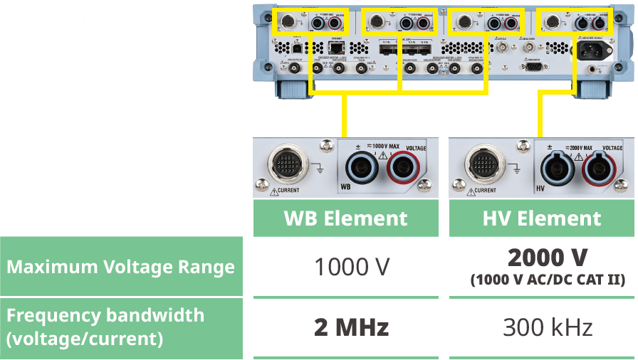
The WT1500 Precision Power Analyzer brings Yokogawa's trusted power measurement performance to production and automated test systems. Combining ±0.038% total power accuracy, direct measurement up to 2000 V, 2 MHz bandwidth, and a compact 2U rack-mount design, it delivers the precision, connectivity, and scalability required for demanding power electronics, motor, and system-level testing.
With up to four power and four motor channels per unit, multi-unit synchronization, and ATE-ready interfaces including CAN/CAN FD, UDP, IEEE 1588, and remote control, the WT1500 integrates easily from a single test station to large multi-channel systems.
High performance
Class-leading ±0.038% total power accuracy, direct 2000 V measurement, and 2 MHz bandwidth support precise evaluation of next-generation power conversion systems
Integrable
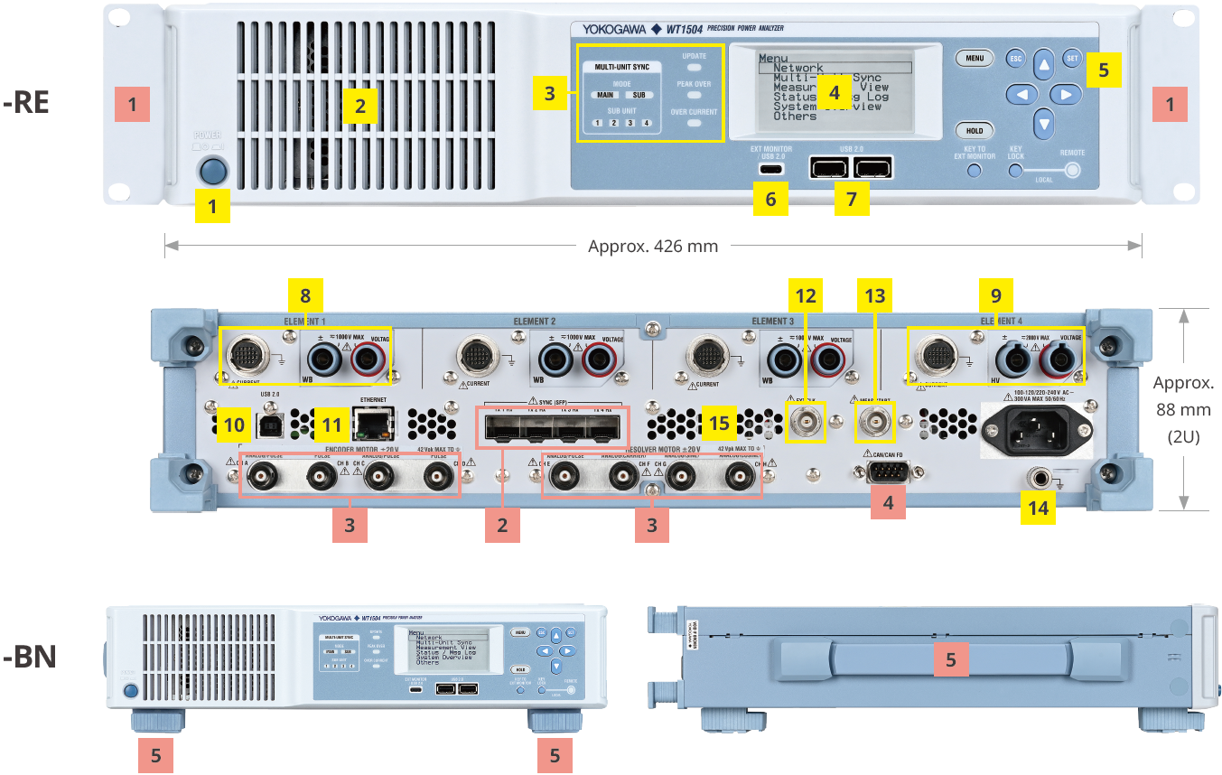
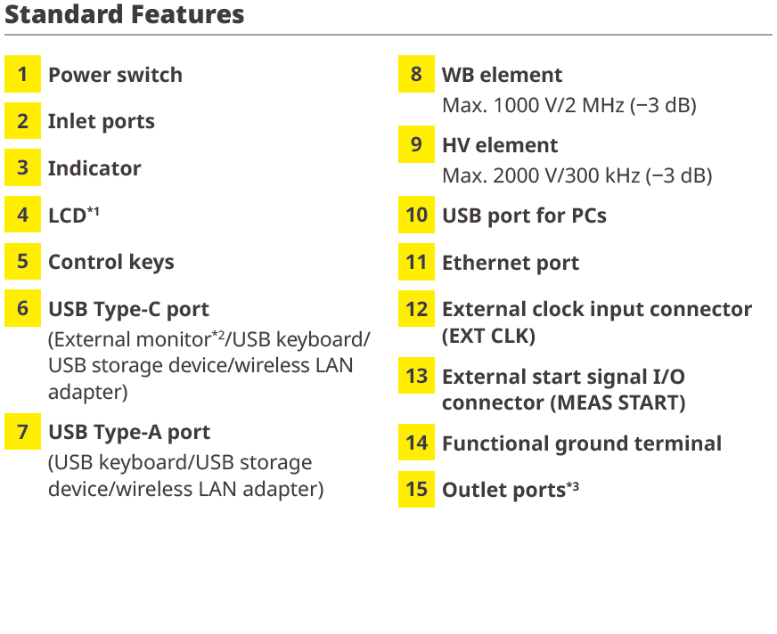
A compact 2U JIS/EIA rack-mount chassis combines four power and four motor channels with CAN/CAN FD, UDP, IEEE 1588, and browser-based remote control for streamlined ATE integration

Scalable
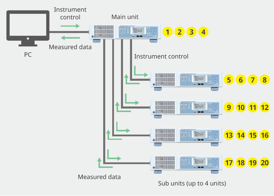
Synchronize up to five units for 20 power and 20 motor channels, with flexible encoder and resolver support for complex multi-motor systems and automated production measurement.
Flexible Motor Analysis with Encoder & Resolver Support
The WT1500 supports flexible motor analysis using both encoder and resolver inputs. Freely mix encoder and resolver channels to evaluate multiple motor types, while built-in Ld/Lq calculations provide advanced analysis for high-efficiency permanent magnet synchronous motors (PMSMs).

Vector diagram of a PMSM
Resolver Input Function for Motor Speed Measurement

Maximize Rack Density with a Compact 2U Design
The WT1500 occupies just 2U (88 mm) in a standard JIS/EIA rack, maximizing valuable cabinet space for additional instruments and test equipment. Rack-mount models are installation-ready, while the benchtop configuration supports standalone operation when needed.

Drop-in installation in standard JIS/EIA test racks

Choose Between Benchtop and Rackmount Versions
CAN data output
Real-time CAN/CAN FD communication streams measurement data directly to host systems, enabling efficient data integration and simplifying system-level evaluation in automated test environments.
* The /CN1 option is required.

Real-Time Data Integration with CAN/CAN FD Output
Low-latency data output via UDP
UDP communication provides continuous, real-time access to measurement data, simplifying system monitoring, accelerating abnormality detection, and supporting simultaneous acquisition from multiple networked instruments.

IEEE 1588 time-synchronized measurement with ScopeCorder waveform capture
IEEE 1588-compliant time synchronization enables precise correlation of WT1500 with compatible instruments, including the SL2000 ScopeCorder, enabling correlated power and waveform measurements with approximately ±10 μs timing accuracy. Timestamped data simplifies event correlation and timing verification.
* The /C40 option of the SL2000 is required.

Auto setup tuned for production signal variation
Built-in auto-setup functions simplify production testing by automatically adapting to changing input signals. Fast 10 ms updates, automatic frequency tracking, low-frequency measurement down to 0.1 Hz, and adaptive filtering ensure stable, accurate measurements without manual adjustment.

Image of operation in auto update mode
Easy connection with a wide range of current sensors, with phase compensation and offset cancellation support
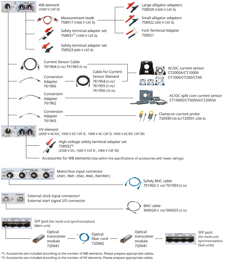
Designed for seamless integration with Yokogawa AC/DC current sensors, the WT1500 automatically recognizes compatible sensors and configures current ratio and phase compensation settings*1. The built-in NULL function compensates for sensor offset, ensuring accurate and repeatable power measurements.
| *1: | When used with sensors that support automatic detection. |
| * | See page 14 for details on accessories. |

Connection examples with various current sensors
Headless control: built-in web server and WTViewerEfree
Remote operation is simplified through the WT1500's built-in web server, enabling browser-based instrument control and measurement monitoring over Ethernet.

Web server
The free WTViewerEfree software adds convenient PC-based control, real-time data visualization, and data transfer for up to two connected WT1500 units*.
* The /SY1 option is required for the WT1500.

WTViewerEfree
External USB-C touchscreen for standalone operation
Connect an external monitor via USB-C to display measurement values, waveforms, and instrument settings. Support for touch-enabled displays provides an intuitive user interface for convenient standalone operation.

Display of measurement values and waveforms with intuitive operation
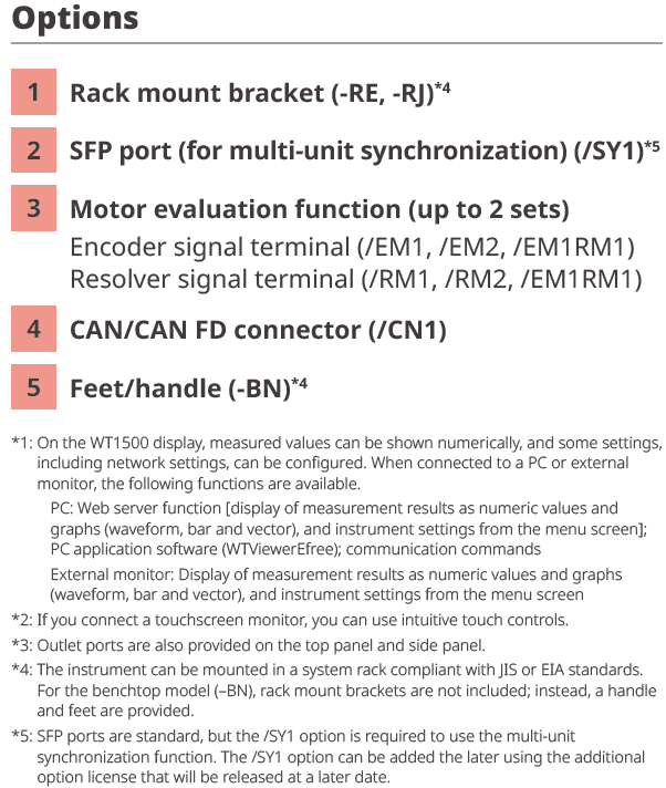
Evaluation of Power Conditioning System (PCS)
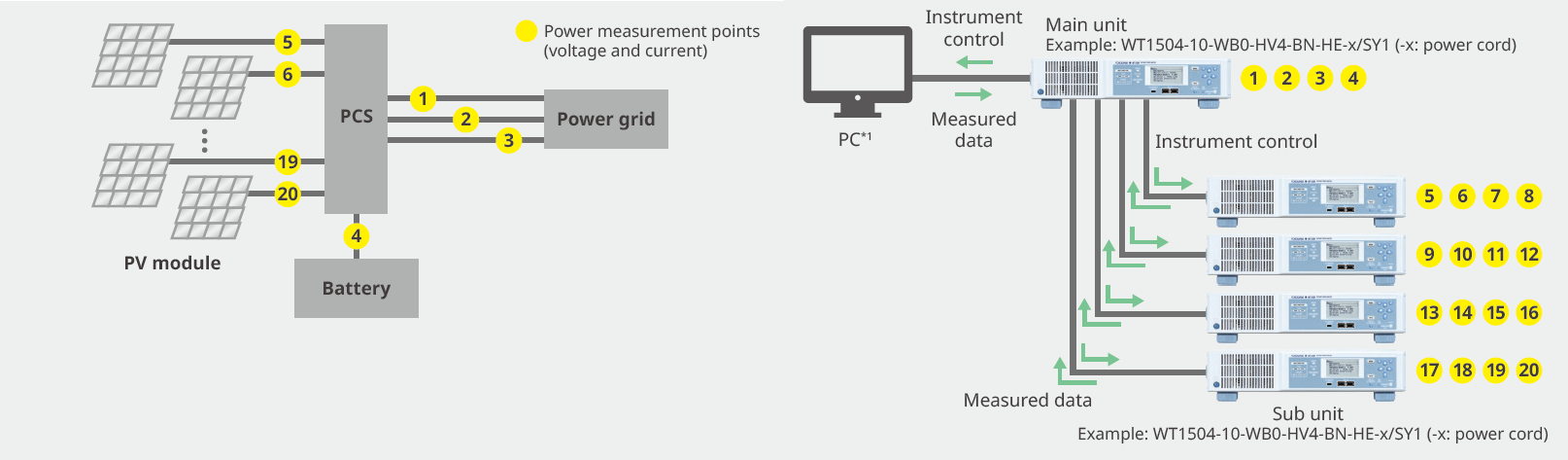
Background/Challenges
Renewable energy systems are moving to higher operating voltages (> 1500 V) and multi-string architectures to improve efficiency and reduce costs. These trends increase the number of measurement points while demanding highly accurate power measurements.
WT1500 Solutions
- High-accuracy power measurement of ±0.038% (DC, 50/60 Hz)*2
- Measure up to 2000 V DC directly*3
- 20 synchronized power channels with centralized control*4
| *1: | Communication commands, web server and WTViewerEfree (free software) can be available. |
| *2: | This is accuracy of the WT1500. Accuracy of current sensor is added to this. |
| *3: | For measurements exceeding 1000 V, use the HV element, the 758932 high-voltage safety terminal adapter, and compatible cables. |
| *4: | The /SY1 option, the 720941 optical transceiver module, and the 720942 optical fiber cord are required. |
Efficiency Evaluation of EV Powertrains
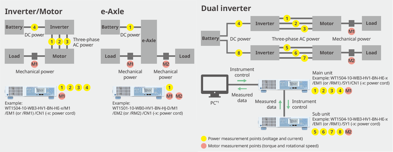
Background/Challenges
EV powertrains are evolving toward integrated e-Axles and dual-inverter architectures to improve efficiency, reduce weight, and simplify system design. These architectures require simultaneous measurement of electrical and mechanical signals, including DC, AC, torque, and speed, across multiple power paths. As the number of measurement points increases, synchronized, high-accuracy multi-channel acquisition and seamless integration with control systems via interfaces such as CAN and CAN FD become essential.
WT1500 Solutions
- High-accuracy power measurement of ±0.038% (DC, 50/60 Hz)*2, with wideband performance up to 2 MHz*3
- Flexible, scalable channel configuration to support multi-inverter and multi-motor testing, with synchronization across multiple units*4
- Simultaneous measurement of electrical and mechanical signals, including support for encoder and resolver inputs*5
- Integrated data output via CAN/CAN FD for seamless connection to ECU and control systems*6
- Low-latency data transfer through UDP communication
| *1: | Communication commands, web server and WTViewerEfree (free software) can be available. |
| *2: | This is accuracy of the WT1500. Accuracy of current sensor is added to this. |
| *3: | A WB element is required. |
| *4: | The /SY1 option, the 720941 optical transceiver module, and the 720942 optical fiber cord are required. |
| *5: | As options, you can select the input signal (encoder or resolver) and the number of motors to be analyzed (1 to 4): /EM1 (up to 2-motor analysis with encoder), /RM1 (1-motor analysis with resolver), /EM2 (up to 4-motor analysis with encoder), /RM2 (up to 2-motor analysis with resolver), or /EM1RM1 (up to 2-motor analysis with encoder and 1-motor analysis with resolver). |
| *6: | The /CN1 option is required. Normal measurement data or harmonic measurement data can be output at each data update interval. |
Energy Efficiency Evaluation of Energy Storage Systems for Data Centers/EV Fast Chargers
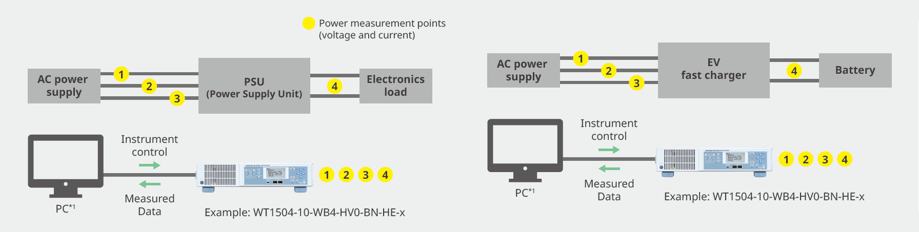
Background/Challenges
High-efficiency power conversion systems, such as AI data center power supplies and EV fast chargers, continue to increase in power density, switching speed, and dynamic load behavior. Accurately evaluating AC/DC conversion efficiency, power flow, and energy transfer is essential to optimize performance, validate efficiency, and ensure reliable operation under both steady-state and rapidly changing load conditions.
WT1500 Solutions
- Power accuracy: ±0.038% (DC, 50/60 Hz)*2
- Measure AC/DC conversion efficiency with a single unit
- Measure power consumption of dynamically changing loads within 1% to 130% of the measurement range
- Measure integrated power (Wh) and integrated current (Ah)
| *1: | Communication commands, web server and WTViewerEfree (free software) can be available. |
| *2: | This is accuracy of the WT1500. Accuracy of current sensor is added to this. |
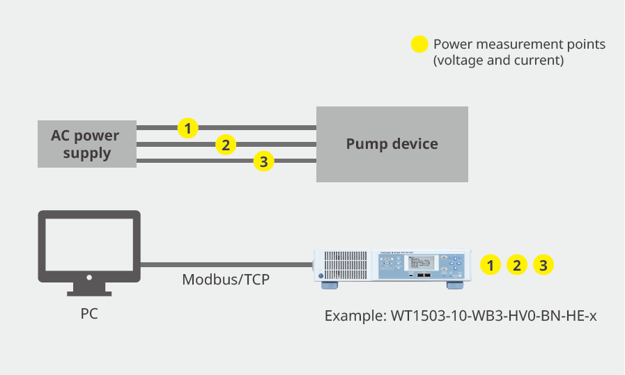
Duration testing and efficiency measurement for industrial motors (pumps & fans)
Background/Challenges
Modern inverter-driven pumps and fans demand accurate long-term evaluation of power consumption, efficiency, and energy usage by monitoring power fluctuations over long periods of time to optimize performance and validate reliability.
WT1500 Solutions
- Long-term integration function (Wh, Ah)
- Support current sensors without an external power supply
- Monitoring is possible via Modbus/TCP communication

E-Antrieb
Gain valuable insight into the performance of electric powertrain systems without second-guessing the quality of your power measurements. From the battery to the motor output and everything in between, Yokogawa instruments enable engineers to confidently and comprehensively analyze electromechanical challenges of EV powertrain systems.

E-Mobilität & Laden
Effectively design and validate electric charging systems, from board to system level. Whether you are benchmarking efficiency, troubleshooting power electronics, or ensuring compliance, explore our suite of solutions for EV charging systems.

Data Center Power Infrastructure
Test and validate server PSUs, rack power systems, GPU workloads, UPS infrastructure, and high-current AI data center power architectures.

Large Capacity/Motor Characterization for Hybrid Car Development


Detailed measurement methods, supply voltage settings, and others are specified for the harmonic/flicker standard test.

Maximum torque per ampere (MTPA) is an optimization strategy for the control of electric motors and drives that employ field-oriented control (FOC), particularly with electric vehicles (EVs) and industrial automation applications. The goal of MTPA is to achieve the maximum possible torque output from a motor for a given current input.


Government agencies that define the standardization of energy efficiency metrics continue to be a driving force behind the development of the next generation electric vehicle powertrains. These metrics require manufacturers to have high confidence in their measurements and motivate the optimization of efficiency.

To use USB interface on the WT500 and WT1800 Power Analyzer from NI LabVIEW environment, you will need to use the USB driver from National Instruments. This USB driver is usually installed when you install NI-VISA and is called the ...
Kataloge & Broschüren
- Features and Benefits Flyer WT1500 (5.3 MB)
- WT1500 Series Precision Power Analyzer (4.9 MB)
- CTS series AC/DC Split core current sensor (5.2 MB)
- CT1000S Split core current sensor (3.2 MB)
Bedienungsanleitungen
- WT1501, WT1502, WT1503, WT1504 Precision Power Analyzer User’s Manual (9.7 MB)
- WT1501, WT1502, WT1503, WT1504 Precision Power Analyzer Getting Started Guide(with supplement) (4.4 MB)
- WT1501, WT1502, WT1503, WT1504 Precision Power Analyzer Communication Interface User’s Manual (2.1 MB)
Datenblätter
Software
Drawings
How-tos

Learn how to transmit measurement results to external devices via a CAN bus and make effective use of power measurement data with the Yokogawa WT1500. This feature helps streamline workflows from measurement to data utilization in development and evaluation environments.

Learn how to measure motor rotational speed using resolver signals. In addition to encoders, the Yokogawa WT1500 can also be utilized for motor evaluation applications that use resolvers.
Suchen Sie mehr Informationen über unsere Mitarbeiter, Technologie oder Lösungen?
Ihr Kontakt zu uns

